
Disclaimer:
This document does not claim any originality and
cannot be used as a substitute for prescribed textbooks. I would like to
acknowledge various sources like freely available materials from internet
particularly NPTEL/ SWAYAM course material from which the lecture note was
prepared. The ownership of the information lies with the respective authors or
institutions. Further, this document is not intended to be used for commercial
purpose and the BlogSpot owner is not accountable for any issues, legal or
otherwise, arising out of use of this document.
This
open resource is a collection of academic course of under graduation program
for B. Tech (Civil Engineering) and M. Tech as per the syllabus of Dr. B.A.T
University, Lonere, Raigad (m.s), India prepared by Dr. Mohd. Zameeruddin,
Associate Professor, at MGM's College of Engineering, Nanded for use in the
out-of-class activity. The content covers both theoretical and analytical
studies. There are six lessons as part of this document, and each deals with an
aspect related to Design of Concrete Structures.
Module
1: Basic Aspects of Structural Design
Module
2: Design of Beams and Slabs [WSM]
Module
3: Design of Columns, Footing and Stairs [WSM]
Module
4: Introduction to Limit State Approach
Module
5: Limit State of Collapse (Flexure)
Module
6: Limit States of Collapse (Shear and Bond)
What is a Structural Engineering?
Structural engineering is a sub-domain of civil engineering wherein the structural components are designed and configured in context to the structural action against design loads to achieve economy and safety for both structure and life (Refer Figure 1).
स्ट्रक्चरल इंजीनियरिंग सिविल इंजीनियरिंग का एक उप-डोमेन है जिसमें संरचना और जीवन दोनों के लिए मितव्ययिता और सुरक्षा प्राप्त करने के लिए डिज़ाइन लोड के विरुद्ध संरचनात्मक कार्रवाई के संदर्भ में संरचनात्मक घटकों को डिज़ाइन और कॉन्फ़िगर किया गया है (चित्र 1 देखें)।

Fig.
1: Glimpse of Modern Structural Engineering Practices
Objectives of Structural Engineering [S Unnikrishna Billai and Devdas Menon, 2003]
- Strength to resist safely the stresses induced by the loads in the various structural members
- Stability to prevent overturning, sliding or buckling of the structure, or parts of it, under the action of loads
- Serviceability to ensure satisfactory performance under service load conditions - which implies providing adequate stiffness and reinforcements to contain deflections, crack-widths and vibrations within acceptable limits, and also providing impermeability and durability (including corrosion-resistance), etc.
Purpose of Structural Analysis and Design
The work of structural designer can be separated in two heads; structural analysis and structural design. The purpose of structural analysis is to determine the resultant stresses and the quantification of displacements (or deformation) in the structural components or structure subjected to given combination of loading (Static or dynamic). The purpose of structural design is to estimate required cross-section of structural components, reinforcement requirements and connection design to withstand the applied loads with safely against serviceability and durability.
Different Types
of Structures
The
structures are classified as (as illustrated in Figure 2);
1. Based
on material used for constructions
- Mud made structures
- Rock/ Stone structures
- Brick masonry structures
- Mortar structures
- Plain concrete structures
- Reinforced concrete structures
- Pre-stressed concrete structures
- Timber structures
- Steel structures
- Composite structures

2. Based
on geometry
(b) 2-Dimensional Structures
(c) 3-Dimensional Structures
(d) Skeletal Structures
3. Based
on the way they carries the loads
- Beams
- Trusses
- Arches
- Cables
- Thin plates
- Plane grids
- Thin shells

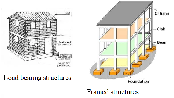
3. Based
on the load path
- Load bearing structures (Slab-Wall-Foundation-Soil)
- Framed structures (Slab-Beam-Column-Foundation-Soil)
- Composite structures (LBS + Framed)
- Retaining Structures (Water tank, Bunkers, Silos and Dams)
- Gravity Structures (Retaining Walls and Dams)
- Offshore Structures (Docks and Harbours)
- Residential Structures
- Multi-Storied Structures
- Industrial Structures
- Transportation Structures
- Monuments
- Public and Recreational Structures
- Military Structures

Fig 2(d): Based on their applications

Reasons for Using
Steel as Reinforcing Material
- The bond between the steel and concrete is greater than other metals
- Strength to weight ratio is greater for steel
- Thermal coefficient of expansion of steel is approximately equal to the thermal coefficient of concrete

- Buildings
- Bridges, Flyovers and Culverts
- Arches and Retaining walls
- Chimneys and Towers
- Water Tanks
- Dams and Barrages
- Docks and Harbours
What is a characteristic
strength of a concrete?
The compressive strength of concrete is given in terms of the characteristic compressive strength of 150 mm size cubes tested at 28 days (fck). As per IS 456-2000, the characteristic strength is defined as that strength of the concrete below which not more than 5% of the tests results are expected to fall. That is there is 5% probability or chance of actual strength being less than the characteristic strength.
There may exits considerable differ between the actual value of cube strength at the site compared to theoretical value or design value of cube strength. This difference may be attributed towards the preparation of concrete mix in the control condition in the laboratory compared to the uncontrolled state of mix preparation on site.
There may exits considerable
differ between the actual value of cube strength at the site compared to
theoretical value or design value of cube strength. This difference may be
attributed towards the preparation of concrete mix in the control condition in
the laboratory compared to the uncontrolled state of mix preparation on site.
These variations in strength are
obtained from the frequency distribution curve by plotting the frequency
ordinates at different intervals. If the obtained variation is normal, the
curve is called normal (Gaussian) distribution curve. The value corresponding
to peak of the curve is called as the mean
value. The
normal distribution curve is symmetrical along both the sides (see figure 5).
The shaded region shows the probability of the fall in the characteristic
strength.

Fig. 5: Normal
(Gaussian) distribution curve for Concrete
The characteristic strength (fck) is obtained as;
fck = fm – kS
Where;
fck is Characteristic
strength
fm is mean
strength
S is standard deviation = √ (observed
deviation) / (No. of samples -1)
k is probability constant (for 5%
equals to 1.64)
Examples
1:
For a project M 20 grade concrete
is decided to be used. The design mixes trails were tested in laboratory. The
results obtained from the test are 21.5, 23.4, 26.2, 17.8, 25.7, 27.1, 22.8,
27.0, 26.4, 25.3, 26.8 and 26.90 (in MPa). Determine the acceptability of mix.
Solution:
|
Sr. No |
Sample Data (f) |
Mean Value (fm) |
Delta (∆) (fm-f) |
Delta (∆2) (fm-f)2 |
Standard Deviation (S) |
|
1 |
21.8 |
24.75 |
-3.15 |
9.92 |
2.85 |
|
2 |
23.4 |
-1.35 |
1.82 |
||
|
3 |
26.2 |
1.45 |
2.10 |
||
|
4 |
17.8 |
-6.95 |
48.30 |
||
|
5 |
25.7 |
0.95 |
0.90 |
||
|
6 |
27.1 |
2.35 |
5.52 |
||
|
7 |
22.8 |
-1.95 |
3.80 |
||
|
8 |
27.0 |
2.25 |
5.06 |
||
|
9 |
26.4 |
1.65 |
2.72 |
||
|
10 |
25.3 |
0.55 |
0.30 |
||
|
11 |
26.8 |
2.05 |
4.20 |
||
|
12 |
26.9 |
2.15 |
4.62 |
||
|
Total |
297 |
|
|
89.29 |
|
Mean value (fm) = 297/12 = 24.75 MPa
Standard deviation = √ ∆2 / (n -1) = √ 89.29/ (12-1) = 2.85
fck = fm – 1.64S = 24.75 -1.64*2.85 = 20.076 MPa
Hence the strength is with the acceptable limits of the assign grade of concrete.
Examples
2:
What should be the average strength of samples of concrete
if desired characteristic strength is 20 N/mm2 and standard deviation
is 4.1 N/mm2.
Solution:
fck = fm – 1.64S
fm = fck + 1.64S = 20 + 1.64*4.1 =
26.724 N/mm2
Properties of Concrete
1. Compressive strength
It may be defined as the capacity of concrete to withstand the compressive load at failure either due to crushing or crippling. It is expressed as the compressive force per unit area of a concrete specimen (in N/mm2 or MPa).
To determine the compressive strength of concrete, cube moulds of size 150mm x 150 mm x 150 mm or cylindrical moulds of diameter 150 mm and height 300 mm are prepared and subjected to the gradual compressive loads. The strength of concrete in compression is affected by the;
a) Specimen slenderness ratio
The experimental results
conducted on the concrete specimens revealed that the compressive strength
reduces as the slenderness ratio increase up to a certain value. When the
slenderness ration (h/d) is equal to or more than 4 the strength remains
constant and equals to 0.67 times the maximum strength.
b) Age effects
Seven day strength of concrete is less than 28 days strength,
because of incomplete hydration of cement. This indicates that the gain of strength
of concrete is dependent on age (measure from day of preparation of mix). Table
1 shows the compressive strength of concrete at various ages.
Table 1: Compressive strength of concrete at various ages (Approximate)
|
Age of concrete |
Strength in percentage of
28 days compressive strength |
|
1 day |
16 |
|
3 day |
40 |
|
7 day |
65 |
|
14 day |
90 |
|
28 day |
99 |
The strength of concrete at 28 days is maximum and adopted
for the design purpose.
c) Water- cement ratio
To complete the hydration of cement 38% water of its weight is needed. If W/C ratio is greater than 38 % it will be of no use. The extra amount of water will get evaporated, thereby leaving pores or voids in concrete affecting the strength of concrete
2. Tensile Strength
Tensile strength of concrete in direct tension is
obtained by testing the concrete cylindrical moulds in the split cylinder test.
It is about 8 to 12 percent of maximum compressive strength of concrete. The
other mode of obtaining the tensile strength is through flexural test where
concrete beam moulds are subjected flexural loads.
The flexural tensile strength (fcr) equals to M/Z
Where; M is the applied moment and Z is elastic
section modulus
IS 456:2000 provides empirical relation for
calculating tensile strength of concrete as fcr
= 0.7√fck (Clause No. 6.2.2
IS 456:2000; IS 516; IS 5816)
3. Modulus of Elasticity
Basically, concrete is inelastic material, but for
design purpose modulus of elasticity of concrete is estimated as Ec
= 5000√fck. Actual measured values may differ by ± 20 percent from the values
obtained from the above expression (Clause No. 6.2.3.1 IS 456:2000).
4. Unit weight
Concrete has ingredients like cement, sand, coarse
aggregates, water and admixture (if needed) in different proportions. Thus,
there is no exact estimation of density of concrete. The density varies in
accordance with unit weight of ingredients. For plain cement concrete it varies
between 20 to 22 KN/m3 and that for reinforced cement concrete is 23
to 26 kN/m3. IS 456:2000 recommends unit weight of plain cement concrete
to be used as 24 kN/m3 and for reinforced cement concrete 25 kN/m3.
What is Reinforcement
Steel?
Rebar,
also known as reinforcement steel and reinforcing steel, is a steel bar or
bundle of steel wires used in reinforced concrete to strengthen and hold the
concrete in tension. To improve the quality of the bond with the concrete, the
surface of reinforcing steel is often patterned.
For the basics of reinforcement and their classification, please refer the Post:
http://mzsengineeringtechnologies.blogspot.com/2015/08/element-of-civil-and-environmental.html
- Main reinforcement: used to provide resistance to support the design loads.
- Distribution
reinforcement: used for durability and aesthetic purposes by providing localized resistance to limit cracking and temperature-induced stresses.
- Anchoring steel: used to assist other steel bars in accommodating their loads by holding them in the correct position.
- Reinforced masonry tie bars to constrain and reinforce masonry structures.
- In the form reinforcing anchors for the grouting and lining.

- Dead loads – IS 875 Part 1
- Live Loads/ Super Imposed Loads– IS 875 Part 2
- Snow Loads– IS 875 Part 4
- Wind Loads– IS 875 Part 3
- Seismic Loads– IS 1893

For
details about types of loading please refer
What do you mean by characteristic loads?
The characteristic load' means that value of load which has a 95 percent probability of not being exceeded during the design life of the structure.
The characteristic load (fk) is obtained as;
fk = fm + kS
Where;
fk is Characteristic
load
fm is mean value of
load
S is standard deviation = √ (observed
deviation (∆2)) / (No. of samples (n) -1)
k is probability constant (for 5% equals to 1.64)
Different component parts of reinforced concrete structures and predominate forces on them
- Working Stress Method (WSM),
- Ultimate Load Method (ULM), and
- Limit State Method (LSM)
To extend this concept of a composite material like a reinforced concrete, strain compatibility (due to bond) is assumed, whereby the strain in the reinforcing steel is assumed to be equal to that in the adjoining concrete to which it is bonded. Furthermore, as the stresses in concrete and steel are assumed to be linearly related to their respective strains, it follows that the stress in the steel is linearly related to that in the adjoining concrete by a constant factor (called the modular ratio), defined as the ratio of the modulus of elasticity of steel to that of concrete. Mathematically, modular ratio (m) = Es/ Ec. Where Es, is modulus of elasticity of steel and Ec, is modulus of elasticity of concrete. The method is also called as “Elastic Method of Design”.
(b) Ultimate Load Method
(ULM)
1. Assessment
of suitable value of load factor so that the value of ultimate load may be determined
corresponding to given working load.
2. Analysis
of structure under the ultimate load so that the distribution of moments and loads
may be determined at failure, and
3.The design of members to fall at moments or forces so determined.
In ULM design the reserve strength in inelastic zone is used, which results in sections with very slender or thin cross-section. A possibility of failure due to cracking or excessive deformation arises, questioning the serviceability requirements.
(c) Limit State Method
Both
the WSM and ULM describes the performance of structural members for working
loads, which is unrealistic and irrational at an ultimate state of collapse. It
is unwarranted in respect of serviceability requirements at service loads. Thus
a new philosophy of combination of both ULM and WSM avoiding demerits has been
emerging out, so called limit state method (LSM).
LSM
may be defined as, “the acceptable limit of safety and serviceability
requirements before failure occurs". Limit state is a stage where whole
structure or part of it becomes unfit for use which may be because of a
collapse or due to formation of collapse mechanism.
This
is taken care by using the resistance of member that it satisfactorily withstands
against applied loads. In this method characteristic value of material strength
and loads are used. Factor of safety applies to both material strength and
loads known as a partial safety factor.
Three types of limit states are considered in the design; (1) Limit state of collapse (safety requirements), (2) Limit state of serviceability, and (3) Limit state of durability [Section 5, IS456:2000].
(1)
Limit State of Collapse
Limit state of collapse is said to be reached, when the part or the whole structure becomes unfit for use due to rupture. This may be because of the failure due to the formation of the mechanism or the elastic/ inelastic failure of the structure. Collapse may be due to flexure, torsion, shear, compression or bond.
(2) Limit State of Serviceability
This is related to the satisfactory behavior of structure at the working loads in the form of (i) limit state of deflection and (ii) limit state of crack.
(i) Limit state of deflection: Excessive deformation in the structure may cause due to lack of safety, spoiling the appearance of the structure. This is taken care by restricting the actual deflection within the permissible limits.
(ii) Limit state of cracking: Cracking of any structural members due to entrance of moisture up to the reinforcement causing corrosion. This is taken care by specifying the maximum crack width for structure.
(3) Limit state of durability:
This is related to the durability of structure withstanding
with natural attacks like fire, chemical action, rain, etc. Depending upon such
action the limit state can be of the following types. Limit state of fire resistance,
Limit state of environmental or chemical action and Limit state of accidental collapse.
Advantages of Ultimate
Load Method over Working Stress Method
Advantages of Limit
State Method over Working Stress Method
References:
- Dr. I. C. Syal and Dr. A. K. Goel. Reinforced Concrete Structures. S Chand and Company Ltd., New Delhi, India
- S Unnikrishna Pillai and Devdas Menon. Reinforced Concrete Design. Tata McGraw-Hill Publishing Company Limited, New Delhi
- N. Subramanian. Design of Reinforced Concrete Structures. Oxford University Press, New Delhi
- IS 456 [1978 and 2000] Indian Standard Plain and Reinforced Concrete- Code of Practice. Bureau of Indian Standards, New Delhi, India


Wonderful blog post sir, very amazing facts and thank you for sharing great experience.
ReplyDeleteSteel Erection Company and Structural Steel Fabrication in Punjab kindly contact us. Structural Steel Fabrication