
Planning for Sustainable Development
Disclaimer:
This document does not claim any originality and
cannot be used as a substitute for prescribed textbooks. I would like to
acknowledge various sources like freely available materials from internet
particularly NPTEL/ SWAYAM course material from which the lecture note was
prepared. The ownership of the information lies with the respective authors or
institutions. Further, this document is not intended to be used for commercial
purpose and the BlogSpot owner is not accountable for any issues, legal or
otherwise, arising out of use of this document.
This open resource is a collection of academic course for the
graduation program for B. Tech (Civil) as per the syllabus of Dr. B.A.T University, Lonere, Raigad (m.s),
India prepared by Dr. Mohd. Zameeruddin, Associate Professor, of MGM's College of Engineering,
Nanded for use of the out-of-class activity. There are six
lessons as part of this document, and each deals with an aspect related to
Planning of Sustainable Development.
Module 1: Sustainable Development-explains and critically evaluates the
concept of sustainable development. Environmental degradation and poverty,
Sustainable development: its main principles, the evolution of ideas about
sustainability
Module 2: Strategies for
promoting sustainable development, resistances to the concept, and some
alternative approaches. Examine some important current issues and areas of
debate in relation to sustainable development
Module 3: Innovation for
sustainable development. Environmental management and innovation strategies
Module 4: Societal transformations.
Institutional theory
Module 5: Governance for
sustainable development. Policy responses to environmental degradation
Introduction:
In the 20th century, as human colonies expanded, new technology were developed for industries, trade, transportation, agriculture, and shelter. The available natural resources and the climate have been significantly impacted by these development activities. The potential and survival of the planet have been called into doubt by this development race (refer fig. 1). To ensure that there is as little impact and pressure on the environment as possible, it is imperative that all of the natural resources that are accessible be managed correctly. The idea of sustainability takes into account such conscientious behavior that guarantees the long-term utilization of resources without endangering the demands of future generations.
The concept of sustainable development is based on the concept of the development (socio-economic development in line with ecological constraints), the concept of needs (re-distribution of resources to ensure the quality of life for all) and the concept of future generations (the possibility of long-term usage of resources to ensure the necessary quality of life for future generations).

Fig
1: Urban development versus sustainable development
(Source NPTEL course, NITTTR, Chennai)
Many of the non-governmental as well as governmental organizations have
embraced sustainable development as the new paradigm of development.
Sustainable development in its present form has become a watchword for
international aid agencies, the jargon of development planners, the theme of
conferences and research papers and slogan for development and environmental
activities. The modern civilization has adopted the concept of sustainability
and prepared a framework of future development. Sustainability has emerged as
the Rosetta stone of biodiversity conservation, development economics,
environmental justice, urban planning and environmental ethics [Andrew D.
Basiago, 1995].
State-of-Art
of the developments in the sustainability concept.
The concept of a sustainable paradigm developed from
international environmental laws and regulations in the 1970s and 1980s. The
development of the sustainability concept can be traced historically to the
major works of:
Definitions of Sustainability

From a philosophical perspective one can identify three main characteristics that determine the core meaning of the modern concept of sustainability and the fundamental issues to which it refers.
1. The meaning of continuance
Refer a certain entity-species, building, capital
Refer a process- to maintain itself


|
Authors |
Year |
Country |
Definition |
|
WCED |
1987 |
United States of America |
“Sustainable
development is meeting the needs of present without compromising the ability
of future generations to meet their needs.”(WCED, 1987). |
|
Pearce, D., Markandya, A.and Barbier, E. |
1989 |
United Kingdom |
“Sustainable
development involves devising a social and economic system, which ensures
that these goals are sustained, i.e. that real incomes rise, that educational
standards increase that the health of the nation improves, and that the
general quality of life is advanced.”(Pearce et al., 1989). |
|
Harwood, R.R |
1990 |
United States of America |
“Sustainable
development is a system that can evolve indefinitely toward greater human
utility, greater efficiency of resource use and a balance with the
environment which is favourable to humans and most other species.”(Harwood,
1990). |
|
Meadows, D. H. |
1998 |
United States of America |
“Sustainable
development is a social construct, referring to the long term evolution of a
hugely complex system – the human population and economy embedded within the
eco-systems and biogeochemical flow of the planet.”(Meadows, 1998) |
|
Van der Merwe, I. and Van der Marwe, J. |
1999 |
Sud Africa |
“Sustainable
development is a program for changing the process of economic development so
that it ensures a basic quality of life for all people and at the same time
protects the ecosystems and community systems that make life possible and
worthwhile.”(Van der Merwe & Van der Marwe, 1999). |
|
Viorel,
H.J. |
2002 |
Romania |
“Sustainable
development is a form of economic growth which satisfies welfare needs of
society in terms of short, medium and long term, it must meet the needs of
the present without, however, compromising the of future
generations.”(Viorel, 2002). |
|
Stefanescu,
F. |
2003 |
Romania |
“Sustainable
development must be understood as a type of economic development that ensures
meeting the needs of present generations without compromising the ability of
future generations to meet their own requirements and applicable measures
aimed at long intervals and long-term effects.” (Stefanescu, 2003). |
|
Beck, U.and Wilms, J. |
2004 |
United Kingdom |
“Sustainable
development is currently a powerful global counter narrative to contemporary
western lifestyles and forms of governing societies.” (Beck & Wilms,
2004) |
|
Hopwood, B., Mellor, M. and O'Brien, G. |
2005 |
United Kingdom |
“Sustainable
development represents a shift in understanding of humanity's place on the
planet, but it is open to interpretation of being anything from almost
meaningless to of extreme importance to humanity.” (Hopwood et al., 2005). |
|
Vare, P. and Scott, W. |
2007 |
United Kingdom |
“Sustainable
development is a process of change, where resources are being gathered, an
investment direction is chosen, the development technologies directed and
various institutions have convergent actions, increasing the potential for
human needs and desires.” (Vare & Scott, 2007). |
|
Sterling, S. |
2010 |
United Kingdom |
“Sustainable
development is seen as reconciliation between economy and environment on a
new path of development that would sustain the human progress not only in a
few places and for a few years, but on the entire planet and for a long
future.” (Sterling, 2010). |
|
Marin, C., Dorobanțu, R., Codreanu D.and Mihaela R. |
2012 |
Romania |
“Sustainability
development refers to the ability of a society, ecosystem, or any such
existing system to operate continuously in an undefined future without
reaching key resource depletion.” (Marin et al., 2012). |
|
Ivascu L. |
2013 |
Romania |
“Sustainable
development can be defined as maintaining system stability by developing a
balance of responsibilities: economic, social, environmental and
technological support technique without compromising the needs of future
generations.” (Ivascu, 2013). |
State-of-Art of the
developments in the sustainability concept
(Ref: M.M.
Shah (2008), Sustainable
Development, in Encyclopedia of Ecology)
The keywords highlighting the need
of concept of sustainability appeared in the publications by Rachel Carson's “Silent
Spring” (1962), Garret Hardin's “Tragedy of the Commons” (1968), “the Blueprint
for Survival” by the Ecologist magazine (1972), and the Club of Rome's “Limits
to Growth report” (1972).

The concept of sustainable development received its first major international recognition in 1972 at the UN Conference on the Human Environment held in Stockholm. The publication highlighted the concerns for preserving and enhancing the environment and its biodiversity to ensure human rights to a healthy and productive world.
The 1982 Nairobi Summit reviewed the progress in the decade since the Stockholm conference and called upon national governments to intensify efforts to protect the environment and stressed the need for international cooperation.
In 1983 the United Nations Commission on Environment and Development was created and in 1987, the Commission issued the Brundtland Report. This report highlighted that equity, growth, and environmental maintenance are simultaneously possible and that each country is capable of achieving its full economic potential while at the same time enhancing its resource base. It emphasized three fundamental components to sustainable development: environmental protection, economic growth, and social equity. It emphasized three fundamental components to sustainable development: environmental protection, economic growth, and social equity.
In 1992, the Earth Summit brought the world’s governments to deliberate and negotiate an agenda for environment and development in the twenty-first century. At a parallel global forum, non-governmental organizations from around the world also discussed and deliberated strategies for sustainable development. While there was little formal interaction between these two meetings, the world’s civil societies succeeded in having their voices noticed. It was an important step toward future dialog and active participation of civil society in sustainable development regimes from local to global levels.
The Earth Summit unanimously adopted the Agenda 21, a comprehensive blue print of actions toward sustainable development, including detailed work plans, goals, responsibilities, and also estimates for funding. Other important accomplishments included the Rio Declaration, a statement of broad principles to guide national conduct on environmental protection and development, and adoption of treaties on climate change and biodiversity, and forest management principles.
The first principle of the Rio Declaration states “human beings are at the center of concerns for sustainable development”. The declaration also highlighted the ‘polluter-pays-principle’ and the ‘precautionary principle’, as important considerations for the protection and conservation of nature. Whether addressing vulnerability to environmental change, responsibility for environmental degradation and loss of biodiversity, or policy priorities, careful consideration of the particular groups of people involved, and their social, economic, and environmental conditions, is essential.
Agenda 21 pointed out that different populations had ‘common but differentiated responsibilities’ for impacts on the environment. In Rio, the thinking was dominated by the goal of converging trends in different parts of the world. There was the clear hope that the developing countries would catch up, while the rich countries would become increasingly environmentally conscious and curb their excessive consumption and the related pollution and waste. This has not come to pass.
The lack of progress in turning Agenda 21 into actions for sustainable development leads to the 2002 Johannesburg World Summit on sustainable development. Johannesburg put the thrust on public–private partnerships for sustainable development through an endorsement of some 500 such partnerships but most of these agreements failed to be implemented.
Prior to the Johannesburg Summit, in September 2000, political leaders from around the world took an unprecedented step of setting concrete 2015 targets for millennium development goals (MDGs) related to the priority challenges of sustainable development, namely, poverty, hunger, education, gender, health, environmental sustainability, and a global partnership for development. All these issues are interrelated; one cannot be solved without tackling the others. The progress up to 2007 indicates that many of these MDGs are unlikely to be realized by 2015.
The nations of the world at the Earth Summit failed to mobilize the financial resources for the implementation of Agenda 21, and the WSSD in Johannesburg failed to turn agenda into actions. The critical issues of education and human capital were also not on the WSSD agenda. The scientific and technological capacity is essential and educational and research institutions around the world have a fundamental responsibility to contribute to this.
In 2012, the United Nations Conference on Sustainable Development met to discuss and develop a set of goals to work toward; they grew out of the Millennium Development Goals that claimed success in reducing global poverty while acknowledging there was still much more to do. The Sustainable Development Goals (SDG) eventually came up with a list of 17 items that included among other things are:
- The end of poverty and hunger
- Better standards of education and healthcare, particularly as it pertains to water quality and better sanitation
- To achieve gender equality
- Sustainable economic growth while promoting jobs and stronger economies
- Sustainability to include health of the land, air, and sea

Table 2: Overview of the various activities related to the concept of sustainable development [Tomislav Klarin, 2018]
|
Year |
Activities |
Brief description |
|
1969 |
UN
published the report Man and His Environment or U Thant Report. |
Activities
focused to avoid global environmental degradation. More than 2,000 scientists
were involved in creation of this report. |
|
1972 |
First
UN and UNEP world Conference
on the Human Environment,
Stockholm, Sweden. |
Under
the slogan Only One Earth, a declaration and action plan for environmental
conservation was published. |
|
1975 |
UNESCO
conference on education about the environment, Belgrade, Yugoslavia. |
Setting
up a global environment educational framework, a statement known as the Belgrade
Charter. |
|
1975 |
International
Congress of the Human Environment (HESC), Kyoto, Japan. |
Emphasized
the same problems as in Stockholm in 1972. |
|
1979 |
The
First World Climate Conference, Geneva, Switzerland. |
Focused
on the creation of the climate change research and programme monitoring. |
|
1981 |
The
first UN Conference on Least Developed Countries, Paris, France. |
A
report with guidelines and measures for helping the underdeveloped countries. |
|
1984 |
Establishment
of United Nations World Commission on Environment and Development (WCED). |
The
task of the Commission is the cooperation between developed and developing
countries and the adoption of global development plans on environmental
conservation. |
|
1987 |
WCED
report Our Common Future or Brundtland report was published. |
A
report with the fundamental principles of the concept of sustainable
development. |
|
1987 |
Montreal
Protocol was published. |
Contains
results of the researches on harmful effects on the ozone layer. |
|
1990 |
The
Second World Climate Conference,
Geneva, Switzerland. |
Further
development of the climate change research and monitoring programme and the
creation of global Climate Change Monitoring System. |
|
1992 |
United
Nations Conference on Environment and Development (Earth Summit or Rio
Conference), Rio de Janeiro, Brazil. |
In
the Rio Declaration and Agenda 21 Action Plan principles of sustainable
development were established and the framework for the future tasks as well. |
|
1997 |
Kyoto
Climate Change Conference, Kyoto, Japan. |
The Kyoto
Protocol was signed between countries to reduce CO2 and other greenhouse
gas emissions, with commencement in 2005. |
|
2000 |
UN
published Millennium declaration. |
Declaration
containing eight Millennium Development Goals (MDGs) set by 2015. |
|
2002 |
The
World Summit on Sustainable Development, Johannesburg, South Africa. |
Report
with the results achieved during the time from the Rio Conference, which
reaffirmed the previous obligations and set the guidelines for implementation
of the concept in the future. |
|
2009 |
The
Third World Climate Conference, Geneva, Switzerland. |
Further
development of the global Climate Change Monitoring System with the aim of
timely anticipation of possible disasters. |
|
2009 |
World
Congress Summit G20, Pittsburgh,
USA. |
G20
member states made an agreement on a moderate and sustainable economy. |
|
2012 |
UN
conference Rio +20, Rio de Janeiro, Brazil. |
Twenty
years from the Rio conference, report The future we want renewed the
commitment to the goals of sustainable development and encouraged issues of
the global green economy. |
|
2015 |
UN
Sustainable Development Summit 2015, New York, SAD. |
The
UN 2030 Agenda for Sustainable Development was published, setting up 17
Millennium Development Goals which should be achieved by 2030. |
|
2015 |
UN
conference on climate change COP21Paris Climate change Conference, Paris,
France. |
Agreement
on the reduction of greenhouse gases in order to reduce and limit global
warming |
Assignment No. 1:
Define the term
sustainability? Brief the state-of-art of development of the concept.
The Real Challenges of Sustainable Development
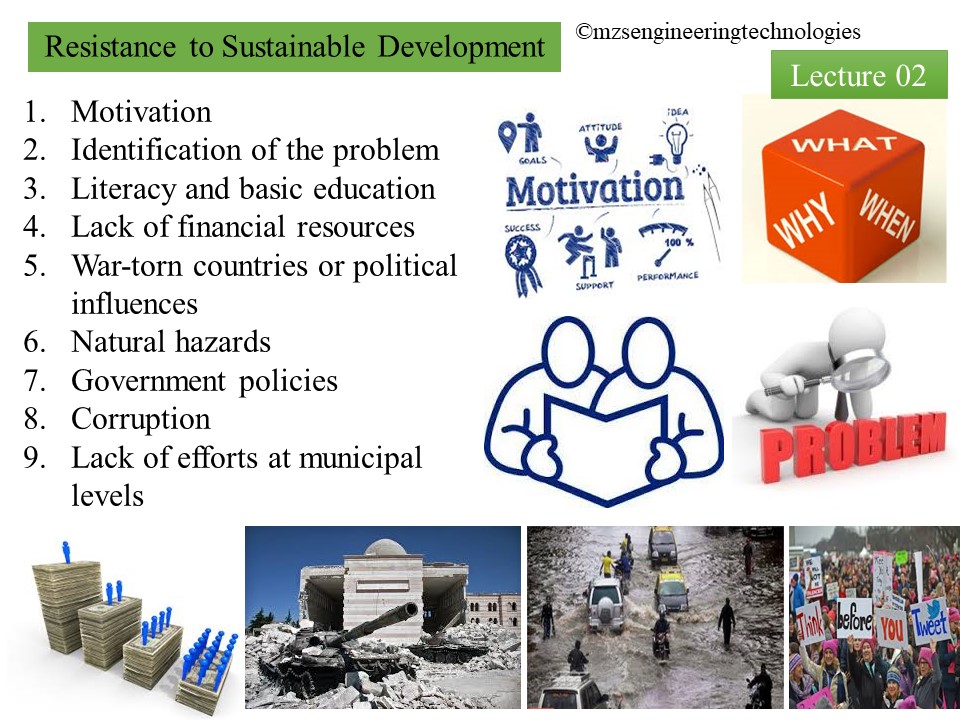
- Poverty and social exclusion
- Lack of
financial resources to carry out and plan sustainable development
- Unemployment
- Climate
change
- Conflict
and humanitarian aid
- Building
peaceful and inclusive societies
- Building strong institutions of governance
- Supporting the rule of law.
Development is a process that creates growth, progress, positive change or the addition of physical, economic, environmental, social and demographic components.
The purpose of development is a rise in the level and quality of life of the population, and the creation or expansion of local regional income and employment opportunities, without damaging the resources of the environment. Development is visible and useful, not necessarily immediately, and includes an aspect of quality change and the creation of conditions for a continuation of that change.
Development,
as a concept, has been associated with diverse meanings, interpretations and theories
from various scholars.
Development
is defined as “an evolutionary process in which the human capacity increases in
terms of initiating new structures, coping with problems, adapting to continuous
change, and striving purposefully and creatively to attain new goals”.
Development
is understood as, “a social condition within a nation, in which the needs of
its population are satisfied by the rational and sustainable use of natural
resources and systems”.
Development
is understood as, “a multidimensional process that involves major changes in
social structures, attitudes, and institutions, as well as economic growth,
reduction of inequality, and eradication of absolute poverty” .

Several
theories have been put forward to explain the concept of development. They
include the Modernization, Dependency, World Systems and Globalization Theories.
The Modernization Theory of development distinguishes between two main categories of societies in the world, namely the traditional and modern societies. The theory, argues that the traditional societies are entangled by norms, beliefs and values, which are hampering their development. Therefore, in order to progress, the traditional societies must emulate the culture of modern societies, which is characterized by accumulation of capital and industrialization which are compatible with development. In essence, this theory seeks to improve the standard of living of traditional societies through economic growth by introducing modern technology. This theory is criticized for not taking into account view of development regarding freedoms and self-esteem.
The Dependency Theory, based on Marxist ideology, debunks the tenets of the modernization theory and asserts that industrialization in the developed countries rather subjects poor countries to under development as a result of the economic surplus of the poor countries being exploited by developed countries. The theory, however, fails to clarify the dependency of the least developed countries on the metropolis in terms of how the developed countries secure access to the economic surplus of the poor countries.
The World Systems Theory posits that international trade specialization and transfer of resources from the periphery (less developed countries) to the core (developed countries) stifle development in the periphery by making them rely on core countries. The World Systems Theory perceives the world economy as an international hierarchy of unequal relations and that the unequal relations in the exchange between the Third World and First World countries are the source of First World surplus. This contrasts with the classical Marxist Theory, which posits that the surplus results from the capital-labor relation that exists in “production” itself. The World System Theory has been criticized for overemphasizing the world market while neglecting forces and relations of production.
The Globalization Theory originates from the global mechanisms of deeper integration of economic transactions among the countries. However, apart from the economic ties, other key elements for development interpretation as far as globalization is concerned are the cultural links among nations, In this cultural orientation, one of the cardinal factors is the increasing flexibility of technology to connect people around the world .

The Concept of Sustainability Development
Having understood the disturbance caused to the environment by
human development and the depletion of natural resources raise the need to keep
it protected for the next generation to do so the concept of sustainable
development has been put forward.
Structurally, the concept
can be seen as a phrase consisting of two words, “sustainable” and “development”
Just as each of the two words that combine to form the concept of SD, that is,
“sustainable” and “development”, has been defined variously from various perspectives,
the concept of sustainable development has also been looked at from various
angles, leading to a plethora of definitions of the concept.
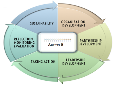
Sustainability and Sustainable Development are analogues and synonyms but the two concepts are distinguishable. Sustainability is the goal or endpoint of a process called sustainable development. While “sustainability” refers to a state, sustainable development refers to the process for achieving this state. Figure l is a "'semantic map" that might help in understanding the concept.

The sustainable development in its present state can be understood
from different definitions, meanings and interpretations.
In a simple
mean sustainable development is a “development that can be continued either
indefinitely or for the given time period.
Sustainable
development is a core concept within global development policy and agenda. It
provides a mechanism through which society can interact with the environment
while not risking or damaging the resource for the future.
It is a
development paradigm as well as a concept that calls for improving living
standards without jeopardizing the earth’s ecosystems or causing environmental
challenges such as deforestation and water and air pollution that can result in
problems such as climate change and extinction of species.
Sustainable
development is an approach to development which uses resources in a way that allows
them (the resources) to continue to exist for others.
Sustainable
development is a concept to the organizing principle for meeting human
development goals while at the same time sustaining the ability of natural
systems to provide the natural resources and ecosystem services upon which the
economy and society depend.
Sustainable
development aims at achieving social progress, environmental equilibrium and
economic growth.
Sustainable development emphasized the need to move away from harmful socio-economic activities and rather engage in activities with positive environmental, economic and social impacts.
- The concept of the development (socio-economic development in line with ecological constraints),
- The concept of needs (re-distribution of resources to ensure the quality of life for all) and
- The concept of future generations (the possibility of long-term usage of resources to ensure the necessary quality of life for future generations).

Assignment
No 2:
- What do you mean by the development? Explain any reference examples.
- Enlist major challenges towards sustainable development
Key Components of Sustainable Development
The key components of sustainability are; human sustainability, social sustainability and economic sustainability.

- Promoting of education, training and public support for the environment.
- Protecting and promoting public health (Viz., medical facilities, risk population and ecological risk)
- Fight against poverty (Ex. Sustainable livelihoods)
- Demographic threatening sustainable development (Ex. Population growth)


The
Three Dimensions of Sustainable Development:
Sustainable development calls for a long-term structural strategy for
the world's economic and social systems, which aims to reduce the burden on the
environment and on natural resources to a permanently viable level, while still
maintaining economic growth and social cohesion. Only development that manages
to balance these three dimensions can be sustained in the long term.
Conversely, ignoring one of the three aspects could potentially endanger the
success of the entire development process.
Sustainable development consists of three dimensions:
- Social solidarity,
- Environmental responsibility and
- Economic efficiency.
Social solidarity:
equality of opportunities for people, involving welfare, quality of life and
sustainable human development –development should liberate individual
capacities and fulfill human needs, thus ending poverty and improving
individuals' quality of life offering a secure life with full rights and
liberties in the long term - and social cohesion.
Environmental
responsibility: the ability to use
natural resources without undermining the equilibrium and integrity of
ecosystems, reduce burden on the environment.
Economic
efficiency: efficiency of economic
and technological activities, foster investment and productivity, economic
growth, economic output potential.
What are the
Sustainable Development Goals?
[Ref: https://www.undp.org ]
The Sustainable Development Goals (SDGs), also known as the Global Goals,
were adopted by all United Nations Member States in 2015 as a universal call to
action to end poverty, protect the planet and ensure that all people enjoy
peace and prosperity by 2030.
The 17 SDGs are integrated—that is, they recognize
that action in one area will affect outcomes in others, and that development
must balance social, economic and environmental sustainability.

Rapid growth in countries such as China and India has lifted millions out of poverty, but progress has been uneven. Women are more likely to be poor than men because they have less paid work, education, and own less property.Progress has also been limited in other regions, such as South Asia and sub-Saharan Africa, which account for 80 percent of those living in extreme poverty. New threats brought on by climate change, conflict and food insecurity, mean even more work is needed to bring people out of poverty.
The SDGs are a bold commitment to finish what we started, and end poverty in all forms and dimensions by 2030. This involves targeting the most vulnerable, increasing basic resources and services, and supporting communities affected by conflict and climate-related disasters.
Goal 2: Zero
hunger
The number of undernourished people has dropped by almost half in the
past two decades because of rapid economic growth and increased agricultural
productivity. Many developing countries that used to suffer from famine and
hunger can now meet their nutritional needs. Central and East Asia, Latin
America and the Caribbean have all made huge progress in eradicating extreme hunger.
Unfortunately, extreme hunger and malnutrition remains
a huge barrier to development in many countries. There are 821 million people
estimated to be chronically undernourished as of 2017, often as a direct
consequence of environmental degradation, drought and biodiversity loss. Over
90 million children under five are dangerously underweight. Undernourishment
and severe food insecurity appear to be increasing in almost all regions of
Africa, as well as in South America.
The SDGs aim to end all forms of hunger and malnutrition by 2030, making sure all people–especially children–have sufficient and nutritious food all year. This involves promoting sustainable agricultural, supporting small-scale farmers and equal access to land, technology and markets. It also requires international cooperation to ensure investment in infrastructure and technology to improve agricultural productivity.
Goal 3: Good
health and well-being
We have made great progress against several leading causes of death and
disease. Life expectancy has increased dramatically; infant and maternal
mortality rates have declined, we’ve turned the tide on HIV and malaria deaths
have halved.
Good health is essential to sustainable development
and the 2030 Agenda reflects the complexity and interconnectedness of the two.
It takes into account widening economic and social inequalities, rapid
urbanization, threats to the climate and the environment, the continuing burden
of HIV and other infectious diseases, and emerging challenges such as non-communicable
diseases.
Universal health coverage will be integral to
achieving SDG 3, ending poverty and reducing inequalities. Emerging global
health priorities not explicitly included in the SDGs, including antimicrobial
resistance, also demand action.
But the world is off-track to achieve the health-related SDGs. Progress
has been uneven, both between and within countries. There’s a 31-year gap
between the countries with the shortest and longest life expectancies. And
while some countries have made impressive gains, national averages hide that
many are being left behind. Multisectoral, rights-based and gender-sensitive
approaches are essential to address inequalities and to build good health for
all.
Goal 4: Quality education
Since 2000, there has been enormous progress in achieving the target of universal primary education. The total enrolment rate in developing regions reached 91 percent in 2015, and the worldwide number of children out of school has dropped by almost half. There has also been a dramatic increase in literacy rates, and many more girls are in school than ever before. These are all remarkable successes. Progress has also been tough in some developing regions due to high levels of poverty, armed conflicts and other emergencies.
In Western Asia and North Africa, ongoing
armed conflict has seen an increase in the number of children out of school.
This is a worrying trend. While Sub-Saharan Africa made the greatest progress
in primary school enrollment among all developing regions – from 52 percent in
1990, up to 78 percent in 2012 – large disparities still remain. Children from
the poorest households are up to four times more likely to be out of school
than those of the richest households. Disparities between rural and urban areas
also remain high.
Achieving inclusive and quality education for all reaffirms the belief
that education is one of the most powerful and proven vehicles for sustainable
development. This goal ensures that all girls and boys complete free primary
and secondary schooling by 2030. It also aims to provide equal access to
affordable vocational training, to eliminate gender and wealth disparities, and
achieve universal access to a quality higher education.
Ending all discrimination against women and girls is not only a basic
human right, it’s crucial for sustainable future; it’s proven that empowering
women and girls helps economic growth and development.
UNDP has made gender equality central to its
work and we’ve seen remarkable progress in the past 20 years. There are more
girls in school now compared to 15 years ago, and most regions have reached
gender parity in primary education.
But although there are more women than ever
in the labour market, there are still large inequalities in some regions, with
women systematically denied the same work rights as men. Sexual violence and
exploitation, the unequal division of unpaid care and domestic work, and
discrimination in public office all remain huge barriers. Climate change and
disasters continue to have a disproportionate effect on women and children, as
do conflict and migration.
It is vital to give women equal rights land and property, sexual and
reproductive health, and to technology and the internet. Today there are more
women in public office than ever before, but encouraging more women leaders
will help achieve greater gender equality.


Societal
Transformation
The
concept of neighbourhood or colonial development emerged after the First World
War. From there, the idea of society was born. A society is a group of
individuals engaged in ongoing social interaction or a large social group
occupying the same social or physical territory, typically subject to the same
governmental authority and dominant cultural norms. The context of society has
changed as a result of technological and commercial advancement. A society goes
through a social change when all facets of life are rebuilt, including
politics, the economics, our way of thinking, and how we live. These little
societies become interconnected throughout time by factors such as necessity
and fear, circumstance, kinship, tradition, beliefs, history, politics,
idealogy, culture, and laws.
प्रथम विश्व युद्ध
के बाद पड़ोस या औपनिवेशिक विकास की अवधारणा उभरी। वहीं से समाज के विचार का जन्म हुआ।
एक समाज चल रहे सामाजिक संपर्क में लगे व्यक्तियों का एक समूह है या एक ही सामाजिक
या भौतिक क्षेत्र पर कब्जा करने वाला एक बड़ा सामाजिक समूह है, जो आमतौर पर एक ही सरकारी
प्राधिकरण और प्रमुख सांस्कृतिक मानदंडों के अधीन होता है। तकनीकी और व्यावसायिक प्रगति
के परिणामस्वरूप समाज का संदर्भ बदल गया है। एक समाज एक सामाजिक परिवर्तन से गुजरता
है जब जीवन के सभी पहलुओं का पुनर्निर्माण किया जाता है, जिसमें राजनीति, अर्थशास्त्र,
हमारे सोचने का तरीका और हम कैसे रहते हैं। ये छोटे समाज समय-समय पर आवश्यकता और भय,
परिस्थिति, रिश्तेदारी, परंपरा, विश्वास, इतिहास, राजनीति, विचारधारा, संस्कृति और
कानूनों जैसे कारकों से एक-दूसरे से जुड़े रहते हैं।

- Define the term sustainability? Discuss the state-of-art of development of the concept.
- What do you mean by the development? Explain any reference examples.
- Enlist major challenges towards sustainable development.
- Enlist the key concept involve in sustainable development matrix.
- State and explain various objectives of sustainable development.
- Write about three pillars of sustainability.
- State and explain various principles of sustainability.
- Describe the dimensions of sustainable development.
- Enlist the primary goals of sustainable development? Explain any two in detail.
- What is environmental degradation? How environmental degradation occurs?
- Write about effects of the major environmental degradation problems.
- Discuss about the suggested solution over environmental degradation issues.
- What is poverty? How it can be associated with sustainable development concept.
- Define the terms: (a) absolute poverty, (b) Secondary poverty, (c) Relative poverty, (d) Asset poverty, and (e) basic needs.
- Explain the role of civil engineer in environmental degradation and poverty sustainable development? With suitable examples.
- How would you define innovation? Describe different approaches to innovation.
- Discuss various styles of innovations.
- What is environmental management? Why it is needed?
- Discuss in detail environmental management principles.
- What do you understand about environmental management plan? State its objectives.
- What is social transformation? Discuss steps involve in societal transformation.
- How does societal transformation happen? Define achieved status and ascribed status gain by an individual.
- What is Governance? What qualities are possessed by good Governance?
- Discuss the role of good governance in sustainable development.
- What is a research? State its objectives? Discuss various types of research.
1. Sharachchandra M LELE (1991). Sustainable
Development: A Critical Review. World Development, Vol. 19(6):607-621. https://doi.org/10.1016/0305-750X(91)90197-P
2. Mensah (2019). Sustainable development: Meaning, history, principles, pillars, and implications for human action: Literature review. Cogent Social Sciences (2019), 5: 1-21. https://doi.org/10.1080/23311886.2019.1653531


