AMAZON GREAT IINDIAN FESTIVAL OFFERS

Monday 10 August 2015

Basic Civil Engineering

Disclaimer:

This document does not claim any originality and cannot be used as a substitute for prescribed textbooks. I would like to acknowledge various sources like freely available materials from internet particularly NPTEL/ SWAYAM course material from which the lecture note was prepared. The ownership of the information lies with the respective authors or institutions. Further, this document is not intended to be used for commercial purpose and the BlogSpot owner is not accountable for any issues, legal or otherwise, arising out of use of this document.

This open resource is a collection of academic course under the graduation program for B. Tech (Civil) prepared as per the syllabus of the Dr. B.A.T University, Lonere, Raigad (m.s), India by Dr. Mohd. Zameeruddin, Associate Professor, of MGM's College of Engineering, Nanded for use in out-of-class activity. The content covers both theoretical and analytical studies. There are six lessons as part of this document, and each deals with an aspect related to the Basics of Civil Engineering. 

Unit 1: Introduction and role of Civil Engineer

Unit 2: Study of Engineering Materials

Unit 3: Component parts of Structures

Unit 4: Surveying and Levelling

Unit 5: Building Planning

Unit 6: Environmental Engineering

 Unit 1: Introduction to Civil Engineering

Civil engineering is the oldest branch of engineering which is growing right from Stone Age civilization. American Society of Civil Engineering (ASCE) defines civil engineering as "the profession in which knowledge of mathematical and physical sciences gained by study, experience, and practice is applied with judgment to develop ways to utilize economically the materials and forces of nature for the progressive well-being of man".

To understand the definition let us have an analogy:

Once, a strong debate held between the various organs of a human body on the topic of superiority. At the start of the debate brain said I am the superior, I send instructions and control messages, you follow it, I memorize the past and present and you follow them.

Heart interrupts saying, no brother, I am superior because if I stop pumping blood you people will not survive. The lungs also added their voice saying we are superior if we stop to breathe, your life will get stopped. Kidneys also get involved in the debate stating the function of purification of blood.

 Meanwhile, skin who was hearing all these statements, feel sorrow about itself that I don't perform any specific task. So I don't have right to stay in the body. Hence get self downed from the body. Suddenly the debate among the organs stopped, as they saw that a Tiger is approaching towards them.

The body starts running from the place. While running the body starts maintaining all organs in their positions by hands, which were getting thrown out. All organs unitedly shout, the skin where are you, you are the superior one, not us. You shaped us, please save us.

In similar way all branches of engineering are good, but one who covers all sectors of society is civil engineering. According to me civil engineering is a civilization. It starts when you wake up and ends when you sleep. A schematic application of civil engineering is shown in Figure 1.

Role of a Civil Engineer

A civil engineer has to conceive, plan, estimate, get approval, create and maintain all civil engineering infrastructure activities. A civil engineer has a very important role in the development of following infrastructures.

1.     To measure and map the earth’s surface.

2.     To plan and develop extensions of towns and cities.

3.     To build the suitable structures for rural and urban areas for various utilities.

4.     To build the tanks and dams to exploit water resources.

5.     To build river navigation and flood control project.

6.     To build canals and distributaries to take water to agricultural fields.

7.     To provide purification and distribution units for freshwater.

8.     To provide and maintain communication system like roads, railways, harbours and airports.

9.     To provide, build and maintain drainage and waste water disposal system.

10.  To monitor land, water, and air pollution and take measures to control them. Fast growing industrialization has put heavy responsibilities on civil engineers to preserve and protect the environment.

Role of civil engineer in the field of; 

Surveying and Levelling 

Surveying is a science and art of determining the relative position of different objects on the surface of the earth, by measuring linear and angular distance, directly or indirectly to prepare a map. In the surveying, the measurement of distance relates to the horizontal plane. Surveying is broadly classified as;

1.     Land Survey

2.     Topography Survey

3.     Cadastral Survey

4.     Engineering Survey

5.     City Surveys

6.     Marine or Hydro graphic Survey

7.     Astronomical Survey

8.     Photographic Survey

9.     GPS Survey


Levelling is the art of determining the relative vertical distances of different objects on the surface of the earth. The levelling relates with the vertical plane in reference to a datum (That is, Mean Sea level, MSL). Levelling is broadly classified as;

1.     Simple Levelling

2.     Differential Levelling

3.     Fly Levelling

4.     Check Levelling

5.     Profile Levelling

6.     Cross Levelling

7.     Reciprocal Levelling

8.     Trigonometric Levelling

9.     Barometric Levelling

10.   Hypsometric Levelling

Figure 2, illustrates application and instruments used in surveying and levelling. With the knowledge of surveying and levelling a civil engineer helps for preparing maps and plans for various applications in engineering projects as listed below;

1.       Land survey for the purpose of taxation and implementation of revenue policies.

2.       Topography survey describing the natural features of area

3.  Route survey for fixing of alignment of proposed route, the location of bridges, culverts, etc.

4.       City and municipal survey for defining cadastral property, zoning, green belts, etc.

5.   Construction survey for the location of material quarries, site drains, marking and layouts, etc.

6.       Hydro-graphical survey for knowing the hydrological details such high flood marks, etc.

7.       The photographic survey used to have an aerial survey of flood-affected areas, dense forest, etc.

8.   Marine Survey to Identify the marine fossils, rock beds, ocean surface, etc.

9.       Mine survey to identify or locate mineral ores, depth, and age of fossils, etc.

10.  Forensic survey and geological survey to find facts related to causes of failures, etc.

With the knowledge of Levelling civil engineer helps in preparing maps and plans for various applications in engineering projects as listed below;

1.  To prepare a contour map for fixing sites for reservoirs, dams, barrages, fix the alignment of roads, railway, irrigation canals, etc.

2.     To determine the altitudes of different important points so as to determine the reduced levels with reference to datum 

3.   To prepare layout plans for water supply, sanitary or drainage


Construction Management

The construction process is a complex activity which involves planning, designing, execution, transportation and storage of materials, equipment, labour.  To have effective and economical construction a civil engineer must possess strong and experienced management skill.

Construction management is the process of planning, coordinating, monitoring and scheduling of a construction activity which is termed as Project planning and Management. Construction management concepts add following advantages to a project;

  1. Optimum utilization of resources.

  2. Reduction in the cost of construction by using best combination of material/ workmanship/ equipment's available.

  3. Achieving balance between the changing environment/ changing demands of market/ changing needs of society.

  4. Building essentials for prosperity of society.

Figure 3, illustrates the role of construction management in a construction project.

Structural Engineering:

Structural engineering is the science and art of designing and making, with economy and elegance, buildings, bridges, dams and other similar structures by utilizing the different combination of materials and geometry so that, they can safely resist the forces to which they may be subjected.

Structures are subjected to various type loads like dead loads, live loads, snow loads, impact loads, wind loads, seismic loads and their combinations. These loads are transferred safely to the ground by predefined load path made by arranging various structural components.

During this transfer structural components are subjected to internal stresses like tension, compression, bending, and torsion. A designer has to ensure that structural member shall be able to sustain applied loads without exceeding limits of stresses and strains. The process of calculating the loads, their combinations, and effects on a structural component or geometry is called as structural analysis. The procedure of estimating the required cross-sectional area of material to sustain applied load within the acceptable limits of safety and serviceability is termed as structural design.

A Civil Engineer during his academic life learns about the forces and their effects, materials and their strength, structural assemblages, geometric configurations and is capable to utilize these skills in the optimization of structural analysis and structural design. The various examples of complex structures design by civil engineers can be identified from the Pyramids of Egypt, Eiffel Tower, to the modern era Burj Khalifa and Bandra-Worli Sea Link.

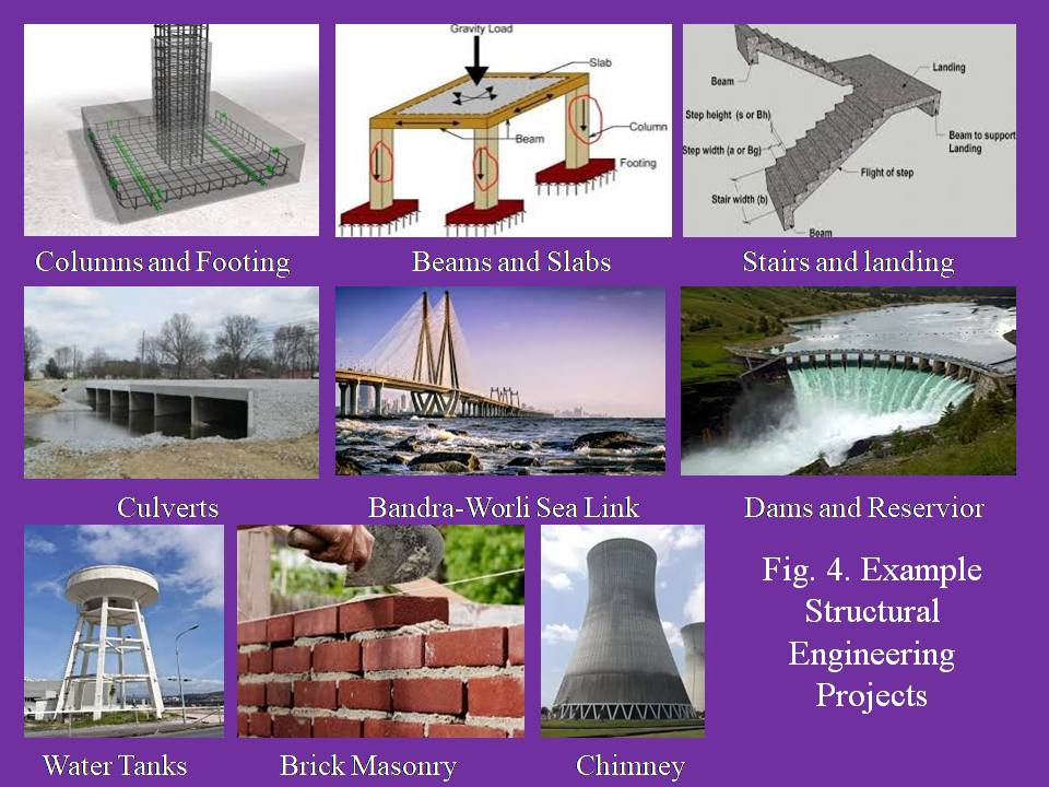
Structural Engineer performs following roles;

  1. Identification and classification of various types of structures.

  2. Estimation of various loads attracted by the structure.

  3. Predicting the limits of safety and serviceability for both material and structural component.

  4. Analysis of different structures and predicting its behaviour.

  5. Design of different structural components and optimization of their geometry

  6. Economical and ease structures

Figure 4, illustrates various structural designs done by a Structural Engineer.

Transportation Engineering:

Transportation Engineering involves the application of scientific and technological principles to any mode of transport, to provide safe, economic and rapid movements of goods and people from one place to another place. Transportation is said to be a backbone of overall progress of any nation which supports economics, social, security and bilateral ties. Figure 5 illustrates the application of transportation engineering. Transportation engineering deals with the study of;

  1. Highway Engineering

  2. Railway Engineering

  3. Airport Engineering

  4. Waterway Engineering

  5. Bridge and Tunnel Engineering

  6. City and Urban roads

  7. Traffic Engineering

  8. Dock and Harbor Engineering

Engineers in this specialization:

  1. Handle the planning, design, construction, and operation of highways, roads, railways, airports, harbors and other vehicular facilities as well as their related bicycle and pedestrian realms.

  2. Estimate the transportation needs of the public and then secure the funding for projects.

  3.  Analyze locations of high traffic volumes and high collisions for safety and capacity. 

  4. Use engineering principles to improve the transportation system. Utilize the three design controls, which are the drivers, the vehicles, and the mode of transport.

Water Resource Engineering:

Among the three basic needs food, water and shelter, water is a vital need. Water available on earth is a gift given by almighty. 71 percent of the world surface is covered with water. Among this available source only 3 percent water is usable. The usable water is available on the earth's surface due to water cycle. During a water cycle the precipitation appears in various forms like mist, dew, rain and snow. This rain water when drops on earth moves back to the ocean. During its journey it gets trapped by surface sources like lakes, ponds and depressions.

       In addition to the use for drinking, water is needed for agriculture, industry, and daily needs. Rains appear in seasonal basis, so water is not available throughout the year. That's why it is needed to store the water, so as to supply it whenever demanded. A civil engineer plays an important role in storage of rain water and its supply. The applied field of civil engineering in water supply and management is (Ref. Figure 6);

1. Water supply Engineering

2. Sanitary Engineering

3. Water resource Engineering

4. Hydraulics

5. Waste water treatment

In water supply engineering, civil engineer is engaged with design, construction and maintenance of a water supply scheme. He evaluates the demand of water, assures quality of water, design of water storage tanks, layout of the distribution system, design of pipes and pumps, design of water treatment plant, and fire hazard outlets.

              The water after the use comes out of the house-hold as a sewage which has to be disposed safely back to the rivers or canals. Before the disposal of this contaminated water it’s require to treat. This treatment process is called as sanitary engineering. In sanitary engineering, civil engineer performs the role of designing of sanitary units, drainage lines, sewer appurtenances, wastewater treatment units.

          Water is not available throughout the year, so proper storage reservoirs are needed. Civil engineers play a role of estimating the quantity of water required to be stored. He identifies the location and catchment areas for required capacity. He designs, artificial brackets like dams, spillways, bandhara across the rivers. He designs the canals for irrigating the fields. He designs the additional sources of outputs from irrigation engineering like hydro-power engineering and lift irrigation units.

         Hydraulic engineering involves the study of mechanics of forces acting on the bodies due to fluids. It involves study of fluid statics and fluid dynamics. A civil engineer does the dimensional analysis, design of pumps, design of turbines, design of hydraulic gates, and analyse the nature of the flow.

        A civil engineer also performs the task of treating the waste water coming from various industrial units, before it being dispose back to streams, channels or rivers.

Geo-technical Engineering:

Geo-technical engineering is a civil engineering discipline that deals with the study of soil and rock behavior in an engineering perspective. The study of the formation of soil and rocks is needed for a civil engineer for the use in the design and construction different structures.

The term "soil" can have different meanings, depending upon the field in which it is has been referred.

To a geologist, it is the material in the relative thin zone of the Earth's surface within which roots occur, and which are formed as the products of past surface processes. The rest of the crust is grouped under the term "rock".

To an agriculturist, it is the substance existing on the surface, which supports plant life. 

To a civil engineer it is a composite of the granular matrix which provides resistance to the heavy loads coming from the structure.

The earth is made of three major parts inner core, outer core and the crust. The crust appears in the form of terrestrial and oceanic crust. The structures are constructed on the surface of terrestrial and ocean crust. The top layer of crust composition of the loose soil, which is fertile one, possesses less strength against heavy loads. As we go deep into the soil the strength of the soil improves, also the structure changes from soft rock to hard rock.

The formation of the rock is classified as sedimentary, metamorphic and igneous. In the Earth's surface, rocks extend up to as much as 20 km depth. The disintegration of rock by the weathering, decomposition and erosion result into the soil mass. The study of the soil formation and rock mechanics is termed as soil mechanics or Geotechnical engineering. With the knowledge of soil mechanics, civil engineer performs the following skill jobs (Refer Fig. 7):

  1. Design and construction of suitable foundation for buildings, bridges, and other infrastructural works
  2. Design and construction of earthen dams and embankments
  3. Design and construction of minor irrigation works like barriers, bunds and canals for irrigation
  4. Design of embankments for highways, railways, helipads and runways
  5. Design and construction of earth retaining structures
  6. Design layout plan for tunneling operation in hills and valleys 

The major soil parameters focused under the soil mechanics and geotechnical engineering is permeability, stiffness, and strength. 

Geology and Seismology:

Unit 2: Study of Engineering Materials

In modern construction of the buildings and other infrastructural developments backed by engineering technology, building materials plays an important role. The building materials cost account about 50 to 80 percent of the total cost of the construction. Hence it becomes important to ensure that they possess the good quality, cheap and easily available. There are some factors which affect the choice of materials for a particular project. These include: (a) Strength, (b) Availability, (c) Durability, (d) Workability, (e) Ease of Transportation, (f) Cost, (g) Aesthetics, (h) Resistance to Fire and (i) Ease of Cleaning. It is very essential for a builder (Architect / Engineer / Contractor/ Owner) to become familiar thoroughly with these building materials.

This building material study includes;

  • Soil, Rocks, Stones and Aggregates
  • Bricks
  • Cement
  • Lime
  • Concrete and Mortar
  • Timber
  • Steel

What is a Concrete?

Concrete is the mechanized mixture of, cement, fine aggregates, coarse aggregates and water in certain proportions which results in  a matrix that hardens (cures) over time and gains a design strength. 

    Concrete is designated in reference to its characteristic strength. For example M 5; where M specifics the mix proportion and 5 shows the compressive strength of cube at an age of 28 days from the day of making a mix.

Concrete mixes are classified as; (a) ordinary concrete, (b) standard concrete and (c) high strength concrete. The classification is based on accuracy of preparation of mixes. Table 1 provides detail classification of all such concrete mixes used in practice.

Table 1: Grades of concrete

Group

Grade designation

Specified characteristic strength of 150 mm cubes at 28 days in MPA

Ordinary Concrete

M10

10

M15

15

M20

20

Standard Concrete

M25

25

M30

30

M35

35

M40

40

M45

45

M50

50

M55

55

High Strength Concrete

M60

60

M65

65

M70

70

M75

75

M80

80


What is a characteristic strength of a concrete?

The compressive strength of concrete is given in terms of the characteristic compressive strength of 150 mm size cubes tested at 28 days (fck). As per IS 456-2000, the characteristic strength is defined as that strength of the concrete below which not more than 5% of the tests results are expected to fall. That is there is 5% probability or chance of actual strength being less than the characteristic strength.

        There may exits considerable differ between the actual value of cube strength at the site compared to theoretical value or design value of cube strength. This difference may be attributed towards the preparation of concrete mix in the control condition in the laboratory compared to the uncontrolled state of mix preparation on site.

    These variations in strength are obtained from the frequency distribution curve by plotting the frequency ordinates at different intervals. If the obtained variation is normal, the curve is called normal (Gaussian) distribution curve. The value corresponding to peak of the curve is called as the mean value. The normal distribution curve is symmetrical along both the sides (see figure 9). The shaded region shows the probability of the fall in the characteristic strength.

Fig. 9: Normal (Gaussian) distribution curve for Concrete

The characteristic strength (fck) is obtained as;

fck = fm – kS

Where;

fck is Characteristic strength

fm is mean strength

S is standard deviation = √ (observed deviation) / (No. of samples -1)

k is probability constant (for 5% equals to 1.64)


1. Soil, Rocks, Stones and Aggregates
Stone

   Stone is a ‘naturally available building material’ which has been used from the early age of civilization. It is available in the form of rocks, which is cut to required size and shape and used as building block. It has been used to construct small residential buildings to large palaces and temples all over the world. The well-known examples of stone buildings are; Red Fort, Taj Mahal, Kutubminar, etc [Bhavikatti, 2010].
Aggregates
     Aggregates is a granular material such as river sand, gravels, crushed stones, crushed hydraulic-cement concrete or blast furnace slag used with hydraulic cementing medium to produce either concrete or mortar. 
              The aggregates are primarily used for providing bulk to the concrete, nearly 70 to 80 percent of the volume of concrete is occupied by aggregates. The reduces shrinkage and effect economy. The study of aggregates involves;
1.      Classification
2.      Source
3.      Size
4.      Shape
5.      Texture
6.      Strength
7.      Specific gravity and bulk density
8.      Moisture content
9.      Bulking factor
10.  Cleanliness
11.  Soundness
12.  Chemical properties
13.  Thermal properties
14.  Durability
15.  Sieve analysis

16.  Grading
1.      Classification
The most common classification of aggregates on the basis of bulk specific gravity is;
(a)    Lightweight aggregates;
(b)   Normal weight aggregates; and
(c)    Heavy-weight aggregates.
    Lightweight aggregates weigh less than 1100 kg/m3. The light weight is due to cellular or high porous microstructure. They have high absorption values. Heavy-weight aggregates weigh more than 2080 kg/m3 and can range up to 4484 kg/m3. Heavy-weights aggregates are commonly used for radiation shielding, counterweights and other applications where high mass to volume ratio is desired. Normal weight aggregates weight range from 1520-1680 kg/m3 and used to produce a normal weight concrete. 
Normal aggregates can further be classified as;
(i)   Natural aggregates:
    These aggregates are obtained from the natural deposit of sand and gravel or from quarries by cutting rocks. Cheapest among them will be the natural sand and gravel which have been reduced to their present size by natural agents such as water, wind, and snow etc. River deposits are the most common and have good quality.
The second most commonly used source of aggregates is quarried bedrock material. Crushed aggregates are made by breaking down natural bedrocks into requisite graded particles through a series of blasting, crushing and screening, etc.
(ii)   Artificial aggregates:
     Amongst the artificial aggregates brick ballast and air-cooled blast furnace slag are most common. Broken brick may be used for mass concrete but is not used for reinforced concrete work unless the crushing strength is high. Blast furnace slag is not commonly used on account of the possible corrosion of steel due to the sulphur content of slag. Concrete made with blast furnace slag aggregate has good fire resisting qualities. Other artificial aggregates such as foamed slag, expanded clay, shale, and slate are also used for producing light weight concrete.
2.      Source
    All the natural aggregates are obtained from the bed rocks. In the earth-crust three exists three types of rocks namely; Igneous, sedimentary, and metamorphic. This classification is made on the basis of the rock formation. The cooling of molten magma or lava on the surface of the crust or deep beneath the crust results in the Igneous rock formation. These rocks are hard, tough, and dense.
Igneous rock or metamorphic rocks are subjected to weathering agencies such as sun, rain, and wind. These weathering agencies decompose, fragmentise, transport and deposit the particle of rock, below the oceanic bed where they are cemented by cementing materials. The cementing material may be carbonaceous, siliceous, or argillaceous in nature.These sedimentary rock formation subsequently get lifted up and becomes continent. The sedimentary rocks are quarried and concrete aggregates are obtained. The sedimentary aggregates vary from soft to hard, porous to dense, and light to heavy.
Both igneous rock and sedimentary rocks may be subjected to high temperature and pressure which causes metamorphism which changes the structure and texture of rocks. Metamorphic rocks possess a foliated structure. The properties of aggregate depend on chemical and mineral composition, petrographic description, specific gravity, hardness, strength, physical and chemical stability, pore structure, etc.
    Igneous rocks: Granite, Dolerite, Basalt etc.
    Sedimentary rocks: Gravel, Sandstone, limestone, Gypsum, Lignite etc.
    Metamorphic rocks: Marble, etc
3.      Size
   These are mineral aggregates which are either obtained from natural sources or produced artificially and may be crushed or uncrushed viz. stone, gravel, sand, blast furnace, slag, furnace clinker etc. These aggregates are used in the production of concrete for normal structural purposes including mass concrete works. These aggregates may be coarse aggregate (C.A.) or fine aggregate (F.A.) or a combination of C.A. and F.A.

a.      Coarse Aggregate
   This consists of aggregate, such as stones, gravels, boulders etc. either crushed or uncrushed but of such a size that most of which (more than 90%) is retained on 4.75 mm IS sieve. Coarse Aggregate is mainly used in production of concrete.

b.      Fine Aggregate

   This consists of sand such as natural sand crushed stone sand, crushed gravel sand or such other inert materials, most of which passes 4.75 mm IS sieve and contains not more than 5% coarser material. This fine aggregate is also used in preparing mortar, plasters etc. in addition to its wide application in the production of concrete.

What is a Concrete?

Concrete is the mechanized mixture of, cement, fine aggregates, coarse aggregates and water in certain proportions which results in  a matrix that hardens (cures) over time and gains a design strength.


Rainwater harvesting

Rainwater harvesting is a technology used for collecting and storing rainwater from rooftops, land surface or catchments/ watersheds using various techniques such as tanks or check dams or recharge of an aquifer. This method provides an alternative source of supplying fresh water during the period of water scarcity and escalating demands. 
The basic components of rainwater harvesting are;
 (i) precipitation, 
(ii) a collection of water
 (iii) water storage, and 
(iv) distribution of water.

Purpose of rainwater harvesting

            Rainwater harvesting technique serves the two main purpose, (a) agricultural, and (b) human consumption. The rain water harvesting provides fresh water, increases groundwater recharge, reduce storm water discharges, urban floods and overloading of sewage treatment plants and reduce sea water ingress in coastal areas.

Rainwater harvesting methodologies 

Rainwater harvesting is under taken through a variety of ways such as; 
1.      Capturing runoff from rooftops – Roof water harvest.
2.      Capturing runoff from local catchments – Land harvest.
3.      Capturing seasonal floodwaters from local streams.
4.      Conserving water through watershed management.

Rooftop rainwater harvesting

It is a system of catching rainwater where it falls. In rooftop harvesting, the roof becomes catchments, and the rainwater is collected from the roof of the house/building. It can either be stored in tank or diverted to artificial recharge system. This method is less expensive and very effective and if implemented properly helps in augmenting the ground water level of the area. The components of rooftop harvesting are shown in Fig. 1. The system mainly constitutes of following sub components; 
1. Catchments; 
2.Transportation; 
3. First Flush 
4. Filter 

Catchments:
The catchment of a water harvesting system is the surface which directly receives the rainfall and provides water to the system. It can be a paved area like a terrace or courtyard of a building, or an unpaved area like a lawn or open ground. A roof made of reinforced cement concrete (RCC), galvanized iron or corrugated sheets can also be used for water harvesting.


COARSE MESH

At the roof to prevent the passage of debris.

GUTTERS
Channels all around the edge of a sloping roof to collect and transport rainwater to the storage tank. Gutters can be semi-circular or rectangular and could be made using:
1.       Locally available material such as plain galvanized iron sheet (20 to 22 gauge), folded to required shapes.
2.      Semi-circular gutters of PVC material can be readily prepared by cutting those pipes into two equal semi-circular channels.
3.       Bamboo or betel trunks cut vertically in half. 

     The size of the gutter should be according to the flow during the highest intensity rain. It is advisable to make them 10 to 15 per cent oversize. Gutters need to be supported so they do not sag or fall off when loaded with water. The way in which gutters are fixed depends on the construction of the house; it is possible to fix iron or timber brackets into the walls, but for houses having wider eaves, some method of attachment to the rafters is necessary.
2. Transportation
    Conduits are pipelines or drains that carry rainwater from the catchment or rooftop area to the harvesting system. Conduits can be of any material like polyvinyl chloride (PVC) or galvanized iron (GI), materials that are commonly available.
3. First-Flushing
     A first flush device is a valve that ensures that runoff from the first spell of rain is flushed out and does not enter the system. This needs to be done since the first spell of rain carries a relatively larger amount of pollutants from the air and catchment surface. 

FILTER


    The filter is used to remove suspended pollutants from rainwater collected over roof. A filter unit is a chamber filled with filtering media such as fiber, coarse sand and gravel layers to remove debris and dirt from water before it enters the storage tank or recharge structure. Charcoal can be added for additional filtration. 

Charcoal water filter
     A simple charcoal filter can be made in a drum or an earthen pot. The filter is made of gravel, sand and charcoal, all of which are easily available.
Sand filters
   Sand filters have commonly available sand as filter media. Sand filters are easy and inexpensive to construct. These filters can be employed for treatment of water to effectively remove turbidity (suspended particles like silt and clay), color and microorganisms.

        In a simple sand filter that can be constructed domestically, the top layer comprises coarse sand followed by a 5-10 mm layer of gravel followed by another 5-25 cm layer of gravel and boulders.

How much water can be harvested?

    The total amount of water that is received in the form of rainfall over an area is called the rainwater endowment of that area. Out of this, the amount that can be effectively harvested is called the water harvesting potential.

Water Harvesting potential = Rainfall (mm) X Collection efficiency

Methods of rooftop water harvesting
1.      Direct use
In this method, rain water is collected from the roof is diverted to storage tank. The storage tank is designed in accordance to the water requirement, rainfall and catchment availability. The conduit should have mesh filter at the mouth and first flush device before connecting to storage tank. Water from storage tank can be used for domestic and gardening purpose.
2.      Recharging ground water aquifers
Ground water aquifers can be recharged by various kinds of structures to ensure percolation of rainwater in the ground instead of draining away from the surface. Commonly used recharging methods are;
a.       Recharging bore wells
b.       Recharge pits
c.       Soak ways or Recharge Shafts
d.      Recharging dug well
e.        Recharge Trench
f.        Percolation Tank
Recharging bore wells

Recharge pits

Soak-ways or Recharge Shafts
2.      Capturing runoff from local catchments – Land harvest.

Percolation tanks

Percolation tanks are the surface tanks, which can be built, in big campuses where land is available and topography is suitable. Surface run-off and roof top water can be diverted to this tank. Water accumulating in the tank percolates in the soil to augment the ground water. The stored water can be used directly for gardening and raw use.


Rainwater harvesting –advantages 
1.      Provides self-sufficiency to water supply
2.      Reduces the cost for pumping of groundwater
3.      Provides high quality water, soft and low in minerals
4.      Improves the quality of ground water through dilution when recharged to groundwater
5.      Reduces soil erosion in urban areas
6.      Rooftop rain water harvesting is less expensive
7.      Rainwater harvesting systems are simple which can be adopted by individuals
8.      Rooftop rain water harvesting systems are easy to construct, operate and maintain.
9.      In hilly terrains, rain water harvesting is preferred
10.  In saline or coastal areas, rain water provides good quality water and when recharged to groundwater, it reduces salinity and also helps in maintaining balance between the fresh-saline water interface 
11.  In Islands, due to limited extent of fresh water aquifers, rain water harvesting is the most preferred source of water for domestic use n In desert, where rain fall is low, rain water harvesting has been providing relief to people

Earthquake Engineering
Introduction

The vibration of the earth produced by the rapid release of strain energy or massive release of strain energy in the form of seismic waves can be term as earthquakes. The energy is stored in the rocks which produces stress and strain until the rock breaking. The underground surface along which the rock breaks and moves is called a fault plane. The earth crust is divided into number of tectonic plates represent the fault zones. The locations of earthquakes throughout the world mark the major tectonic boundaries. The movement between plates and along faults is not smooth. The plates move in jerks, giving rise to earthquakes. The movement of Earth’s plates creates powerful forces that Squeeze or Pull the rock in the crust. Thus earthquake can be defined as;


“The shaking that results from the movement of rock beneath Earth’s surface”

Structure of the Earth
Earth is spheroidal in shape with an approximate diameter of 12756 km (or radius of 6375 km) formed about 4500 million years back. The earth can be divided into three layers as;
1   1.      Core
a.       Inner core (Solid)
b.      Outer Core (Viscous)
2   2.      Mantle
3   3.      Crust
     The Earth has an outer silica-rich, solid crust, a highly viscous mantle, and a core comprising a liquid outer core that is much less viscous than the mantle, and a solid inner core.
The inner core is a primarily solid sphere about 1220 km in radius situated at Earth's center. The temperature is estimated at 5,000- 6,000 degrees Celsius and the pressure to be about 330 to 360 Gpa (which is over 30lakhs times that of the atmosphere).

The mantle is approximately 2,900 km thick and comprises 70% of Earth's volume. The core makes up about 30% of Earth's volume, with the outer crust [where we live] <1%. In the mantle, temperatures range between 500-900 degrees Celsius at the upper boundary with the crust to over 4,000 degrees Celsius at the boundary with the core.
The outer most layer is the crust - this is the most familiar to us as it is where we live. The distinction between crust and mantle is based on chemistry, rock types and seismic characteristics. The crust is made of continental crust and oceanic crust,
The continental Crust has a thickness of 10-70km, less dense than oceanic crust and mostly old.
The oceanic crust is thin approximately 7 km, dense and young compare to continental crust.

Fig. 2. Component parts of earth crust
Technical terms
Focus:
The initial rupture point of an earthquake, where strain energy is first converted to elastic wave energy is said to be focus or the point on the fault where slip starts is the Focus or Hypocenter or
The point within the earth which is the center of an earthquake.
Epicenter:

The point on Earth’s surface directly above an earthquake’s focus. The depth of focus from the epicenter, called as Focal Depth, is an important parameter in determining the damaging potential of an earthquake.
Epicentral distance:
Distance from epicenter to any point of interest is called epicentral distance. For earthquakes at large distances, sometimes epicentral distance is measured as an angle subtended at the center of the Earth
Focal depth:
The depth of focus from the epicenter, called as Focal Depth, is an important parameter in determining the damaging potential of an earthquake.

 Detecting Seismic Waves

A device that records ground movements caused by seismic waves as they move through earth is known as Seismograph or Seismometer.


It a mechanical device which consist of a   heavy weight attaches to a frame by means of a spring or wire. A pen connected to the weight rests its point on a rotating drum. During an earthquake the seismic waves cause the drum Seismometers to shake while the pen stays in place. The pen records lines on the paper around the drum. If the earth moves (in this case from left to right) the whole machine will vibrate too.
Types of waves released during an earthquake:

Earthquake shaking and damage is the result of three basic types of elastic waves. Two of the three propagate within a body of rock. The faster of these body waves is called the primary or P wave. Its motion is the same as that of a sound wave in that, as it spreads out, it alternately pushes (compresses) and pulls (dilates) the rock. These P waves are able to travel through both solid rock, such as Granite Mountains, and liquid material, such as volcanic magma and the water of the oceans.

The slower wave through the body of rock is called the secondary or S wave. As an S wave propagates, it shears the rock sideways at right angles to the direction of travel. If a liquid is sheared sideways or twisted, it will not spring back, hence S waves cannot propagate in the liquid parts of the earth, such as oceans and lakes.

The actual speed of P and S seismic waves depends on the density and elastic properties of the rocks and soil through which they pass. In most earthquakes, the P waves are felt first. The effect is similar to a sonic boom that bumps and rattles windows. Some seconds later, the S waves arrive with their up-and-down and side-to-side motion, shaking the ground surface vertically and horizontally. This is the wave motion that is so damaging to structures.

The third general type of earthquake wave is called a surface wave, reason being is that its motion is restricted to near the ground surface. Such waves correspond to ripples of water that travel across a lake.


Surface waves in earthquakes can be divided into two types. The first is called a Love wave. Its motion is essentially that of S waves that have no vertical displacement; it moves the ground from side to side in a horizontal plane but at right angles to the direction of propagation. The horizontal shaking of Love waves is practically damaging to the foundations of structures. The second type of surface wave is known as a Rayleigh wave. Like rolling ocean waves, Rayleigh waves wave move both vertically and horizontally in a vertical plane pointed in the direction in which the waves are travelling.
Surface waves travel more slowly than body waves (P and S); and of the two surface waves, Love waves generally travel faster than Rayleigh waves. Love waves (do not propagate through water) can effect surface water only insofar as the sides of lakes and ocean bays pushing water sideways like the sides of a vibrating tank, whereas Rayleigh waves, because of their vertical component of their motion can affect the bodies of water such as lakes.

P and S waves have a characteristic which effects shaking: when they move through layers of rock in the crust, they are reflected or refracted at the interfaces between rock types. Whenever either wave is refracted or reflected, some of the energy of one type is converted to waves of the other type. A common example; a P wave travels upwards and strikes the bottom of a layer of alluvium, part of its energy will pass upward through the alluvium as a P wave and part will pass upward as the converted S-wave motion. Noting also that part of the energy will also be reflected back downward as P and S waves.
Procedure for locating an epicenter:

The information recorded from seismometers located at three separate station are used to locate the epicenter. Following procedure is adopted;
1.      Study the seismographs and find the elapsed time between the arrival of the first P-wave and the first S-wave.

2.      Using a time-distance graph you can find the distance to the epicenter from the seismic station.
3.      Now on a map draw circle around the epicenter, in which radius
4.      The point at which the tree circles meet is the epicenter.
Measurement of earthquake:
The measurement of an earthquake’s is based on its magnitude and intensity. Magnitude of earthquake is a measure of earthquake’s strength is based on seismic waves and movement along faults. Intensity is measure of the strength of ground movement in a given place. There are a number of ways to measure the magnitude of an earthquake.


The first widely-used method, the Richter scale, was developed by Charles F. Richter in 1934. It used a formula based on amplitude of the largest wave recorded on a specific type of seismometer and the distance between the earthquake and the seismometer. It is a logarithmic scale, which means each level has 10 times the magnitude of the level below it. 

That scale was specific to California earthquakes; other scales, based on wave amplitudes and total earthquake duration, were developed for use in other situations and they were designed to be consistent with Richter’s scale.

Mercalli Scale

Another way to measure the strength of an earthquake is to use the Mercalli scale. Invented by Giuseppe Mercalli in 1902, this scale uses the observations of the people who experienced the earthquake to estimate its intensity. 

The Mercalli scale isn't considered as scientific as the Richter scale, though. Some witnesses of the earthquake might exaggerate just how bad things were during the earthquake and you may not find two witnesses who agree on what happened; everybody will say something different. The amount of damage caused by the earthquake may not accurately record how strong it was either.

The Mercalli scale has 12 steps and describes how an earthquake affects People, Buildings, and the Land Surface.

Causes of earthquake
Earthquakes are usually caused when rock underground suddenly breaks along a fault. This sudden release of energy causes the seismic waves that make the ground shake. When two blocks of rock or two plates are rubbing against each other, they stick a little. The various causes are;
1.   Stress
A force (push or pull) that acts on rock to change its shape or volume. Compression is stress that squeezes rock until it folds or breaks. Tension is stress that stretches rock so that it becomes thinner in the middle. Shearing stress is that pushes a mass of a rock in opposite, horizontal directions.
2.      Deformation
A change in the volume or shape of Earth’s crust (which causes it to bend, stretch, break, tilt, fold or slide). Most changes in the crust occur so slowly that they cannot be observed directly. Rocks on both sides of the fault can move up or down, or sideways.

3.      Due to construction of large dams, big reservoir near to the faults
4.      The movement between tectonic plates and along faults is not smooth. The plates move in jerks, giving rise to earthquakes.

Effects of earthquakes
1.      If the intensity of earthquake is less, only shaking of the earth takes place.
2.    If the intensity of earthquake is moderate all type of structure vibrates resulting in structural damages, casualties and downtime of uses of structure.
3.  The severe shaking provided by seismic waves can damage or destroy buildings and bridges, topple utility poles, and damage gas and water mains
4. The earthquake may cause land sliding.
5. The earthquake may cause outbreak of fires due to damages to oil and gas pipelines.
6.The earthquake can cause topping of water in seas, oceans called as Tsunamis.
7. The earthquake changes the water table i.e.; it may become shallow or deepen down. 
8. The earthquake damages the infrastructure of a country such as bridges, dams, roads, railway tracks, etc.
9.  A severe earthquake may change the river bed slope, change its direction of flow, etc.
Precautions to be taken before earthquakes
1. Make sure you have a fire extinguisher, first aid kit, a battery-powered radio, a flashlight, and extra batteries at home.
2. Learn first aid.
3. Learn how to turn off the gas, water, and electricity.
4. Make up a plan of where to meet your family after an earthquake.
5. Don't leave heavy objects on shelves (they'll fall during a quake).
6. Anchor heavy furniture, cupboards, and appliances to the walls or floor.
7. Learn the earthquake plan at your school or workplace.
Precautions to be taken during earthquakes
1. Stay calm! If you're indoors, stay inside. If you're outside, stay outside. 
2. If you're indoors, stand against a wall near the center of the building, stand in a doorway, or crawl under heavy furniture (a desk or table). Stay away from windows and outside doors.
3, If you're outdoors, stay in the open away from power lines or anything that might fall. Stay away from buildings (stuff might fall off the building or the building could fall on you).
4. Don't use matches, candles, or any flame. Broken gas lines and fire don't mix.
5. If you're in a car, stop the car and stay inside the car until the earthquake stops.
6. Don't use elevators (they'll probably get stuck anyway).
Precautions to be taken after earthquakes
1Check yourself and others for injuries. Provide first aid for anyone who needs it. 
2. Check water, gas, and electric lines for damage. If any are damaged, shut off the valves. Check for the smell of gas. If you smell it, open all the windows and doors, leave immediately, and report it to the authorities (use someone else's phone). 
3. Turn on the radio. Don't use the phone unless it's an emergency.
4. Stay out of damaged buildings.
5. Be careful around broken glass and debris. Wear boots or sturdy shoes to keep from cutting your feet.
6. Be careful of chimneys (they may fall on you).
7. Stay away from beaches. Tsunamis and seiches sometimes hit after the ground has stopped shaking.
8. Stay away from damaged areas.
9. If you're at school or work, follow the emergency plan or the instructions of the person in charge.
10. Expect aftershocks.
Zone of earthquake in India
Based on historic data of earthquake, India is divided in to 5 zones. Zone I is of very mild earthquake and zone V is severest zone of earthquake. 

Zone I
Very mild earthquake, places are, part of Karnataka, Andhra Pradesh, Madhya Pradesh,
Rajasthan, Maharashtra, etc. 
Zone II
Mild earthquake, places are part of Karnataka, Andhra Pradesh, Tamil Naidu, Maharashtra,
Rajasthan, and Madhya Pradesh, etc.
Zone III
Medium range earthquake, places are, part of Maharashtra (Marathwada), Karnataka, Andhra
Pradesh, Andaman and Nikobar islands, Western Himalayas, etc.
Zone IV 
High range of earthquake, Places are Indo-Gangatic plane (Part of Bihar, Uttar Pradesh), part of  
Delhi, Jammu and Kashmir, Gujarat, Maharashtra, etc.
Zone V
Very high range of earthquake, places are part of Jammu and Kashmir, Punjab, Western and  
Central Himalaya, North-East region and Rann of Kutch (Gujarat). 
General design consideration for construction of building in seismic zone
Following general design considerations are desirable in seismic zone;
1. Building should be symmetric in plan and elevation.
2.      Frame structure are preferred over load bearing frame, even for low rise structure.
3.      Structures should not be brittle or collapse suddenly. Rather, they should be tough, able to deflect or deform a considerable amount.
4.      Resisting elements, such as bracing or shear walls, must be provided evenly throughout the building, in both directions side-to-side, as well as top to bottom.
5.      All elements, such as walls and the roof, should be tied together so as to act as an integrated unit during earthquake shaking, transferring forces across connections and preventing separation.
6.      The building must be well connected to a good foundation and the earth. Wet, soft soils should be avoided, and the foundation must be well tied together, as well as tied to the wall. where soft soils cannot be avoided, special strengthening must be provided.
7.      Care must be taken that all materials used are of good quality, and are protected from rain, sun, insects and other weakening actions, so that their strength lasts.
8.      Unreinforced earth and masonry have no reliable strength in tension, and are brittle in compression. Generally, they must be suitably reinforced by steel or wood.
Earthquake resistant low cost building
All traditional earthquake-resistant construction technologies provide the building with the 
capacity to withstand large earthquake forces without catastrophic collapse, from structural
behavior consideration, these technologies can be divided into the following general categories:
1.  Construction technologies using ductile construction materials- such as building made of timber and bamboo.
2.      Construction technologies using robust architectural, forms such as buildings with symmetric plan and elevation.
3.   Construction technologies using resilient structural configuration –such as buildings with bands and braces.
4.  Construction technologies reducing seismic forces- such as through use of light- weight members.
1.      Mud walled house
      In most of the rural areas of India, rural houses are characterized by mud walled. Sometimes walls are made of sun dried earthen blocks of one to two feet thickness. These mud walled houses are generally oblong in shape and covered with the roofs made with clay tiles, thatch or corrugated iron sheets. The application of these construction materials depends on their availability and the ability of the house owners. In these specific regions the lands are normally above flood level. Besides this, relatively less rainfall, dry climate and lateritic soil (which gets very hard when dry) are the main reasons behind the mud constructions
2.      Bamboo walled house
    In the piedmont alluvial plains, especially in rangpur , moribund delta area in jessore and haor basins, flood plains of the Ganges, the Yamuna, the Brahmaputra, the Meghan, the tista and in some areas in eastern and northern regions, the walls are generally made of bamboo and rooms are configured in rectangular shape. Bamboo is used for making posts and enclosing elements, which is called ‘bera’ sometimes timber is used for the post and making an upper horizontal floor in the room.
3.      Timber house
    Relatively small groups of populations are using the house forms having walls constructed with timber. Generally, the houses are built on raised wooden platform to get safety from snakes and other animals. The lower parts of the houses are also used for various purposes like storage, keeping domestic animals, different family activities etc.
4.      Timber and brick built house
     The timber and brick built houses are common in India. The floors ,plinths and the lower parts of the walls are constructed with brick while the rest portion of the walls are constructed with bamboo reeds covered with cement or mud on the both sides.
5.      Corrugated iron (C.I) sheet built house
    C.I. sheet was not being used as the indigenous building material. Later on, for its durability, it becomes one of the major building materials in local tradition. It is very common to build houses (walls and roofs) with corrugated iron sheets. Corrugated iron sheets are providing protection against rain and dampness of the weather.


TIMBER

Timber refers to wood used for construction works.

- A tree that yields good wood for construction is called ‘Standing Timber.

- After felling a tree, its branches are cut and its stem is roughly converted into pieces of suitable length, so that it can be transported to timber yard. This form of timber is known as “rough timber”.

-  By sawing, rough timber is converted into various commercial sizes like planks, battens, posts, beams etc. Such form of timber is known as “converted timber”.

Classification of Timber


The following are the important basis for classification;
(i) Mode of growth
(ii) Modulus of elasticity
(iii) Durability
(iv) Grading
(v) Availability.

Classification Based on Mode of Growth

On the basis of mode of growth trees are classified as;
 (aExogenous and (bEndogenous


a. Exogenous

These trees grow outward by adding distinct consecutive ring every year. These rings are known as annual rings. Hence it is possible to find the age of timber by counting these annual rings. These trees may be further divided into (1) coniferous and (2) deciduous.

Coniferous trees are having cone shaped leaves and fruits. The leaves do not fall till new ones are grown. They yield soft wood.

Deciduous trees are having broad leaves. These leaves fall in autumn and new ones appear in springs. They yield strong wood and hence they are commonly used in building construction.


Endogenous

These trees grow inwards. Fresh fibrous mass is in the inner most portion. Examples of endogenous trees are bamboo and cane. They are not useful for structural works.

Classification Based on Modulus of Elasticity

Young’s modulus is determined by conducting bending test. On this basis timber is classified as;
Group A:         E = 12.5 kN/mm2
Group B:         E = 9.8 kN/mm2 to 12.5 kN/mm2
Group C:         E = 5.6 kN/mm2 to 9.8 kN/mm2.
Classification Based on Durability

Durability tests are conducted by the forest research establishment. They bury test specimen of size 600 × 50 × 50 mm in the ground to half their length and observe their conditions regularly over several years. Then timbers are classified as;

High durability:           If average life is more than 10 years.
Moderate durability:    Average life between 5 to 10 years.
Low durability:            Average life less than 5 years.

Classification Based on Grading

IS 883-1970 classifies the structural timber into three grades-select grade, grade I and grade II. The classification is based on permissible stresses, defects etc.

Various defects which are likely to occur in timber may be grouped into the following three:
(i) Due to natural forces
(ii) Due to defective seasoning and conversions.
(iii) Due to attack by fungi and insects.

 Defects due to Natural Forces

a)   Knots: When a tree grows, many of its branches fall and the stump of these branches in the trunk is covered. In the sawn pieces of timber the stump of fallen branches appear as knots. Knots are dark and hard pieces. Grains are distorted in this portion.

b)   Shakes: The shakes are cracks in the timber which appear due to excessive heat, frost or twisting due to wind during the growth of a tree. Depending upon the shape and the positions shakes can be classified as star shake, cup shake, ring shakes and heart shakes

c)   Wind cracks: These are the cracks on the outside of a log due to the shrinkage of the exterior.

d)   Upsets: This type of defect is due to excessive compression in the tree when it was young. 
                  Upset is an injury by crushing. This is also known as rupture.

Properties of Timber

Properties of good timbers are;

Colour: It should be uniform.
Odour: It should be pleasant when cut freshly.
Soundness: A clear ringing sound when struck indicates the timber is good.
Texture: Texture of good timber is fine and even.
Grains: In good timber grains are close.
Density: Higher the density stronger is the timber.
Hardness: Harder timbers are strong and durable.
Warping: Good timber do not warp under changing environmental conditions.
Toughness: Timber should be capable of resisting shock loads.
Abrasion: Good timber do not deteriorate due to wear. This property should be looked into, if timber is to be used for flooring.
Strength: Timber should have high strength in bending, shear and direct compression.
Modulus of Elasticity: Timber with higher modulus of elasticity are preferred in construction.
Fire resistance: A good timber should have high resistance to fire.
Permeability: Good timber has low water permeability.
Workability: Timber should be easily workable. It should not clog the saw.
Durability: Good timber is one which is capable of resisting the action of fungi and insects attack
Defects: Good timber is free from defects like dead knots, shakes and cracks.

Uses of Timber

Timber is used for the following works;
1. For heavy construction works like columns, trusses, piles.
2. For light construction works like doors, windows, flooring and roofing.
3. For other permanent works like for railway sleepers, fencing poles, electric poles and gates.
4. For temporary works in construction like scaffolding, centering, shoring and strutting, packing
of materials.
5. For decorative works like showcases and furnitures.
6. For body works of buses, lorries, trains and boats
7. For industrial uses like pulps (used in making papers), card boards, wall papers
8. For making sports goods and musical instruments.

TYPES OF LOADS ON STRUCTURE

Classification of Loads

The loads are broadly classified as;
  1. Vertical loads,
  2. Horizontal loads, and
  3. Longitudinal loads.
ü  The vertical loads consist of dead load, live load and impact load.
ü  The horizontal loads comprises of wind load and earthquake load.
      ü  The longitudinal loads i.e. tractive and braking forces are considered in special case of design
          of bridges, gantry girders etc.

Structural loads

A load may be defined as a force tending to effect and produce deformations, stresses or displacements in the structure


Types of Loads in Structures


  1. Dead loads
  2. Live loads
  3. Dynamic loads
  4. Wind loads
  5. Earthquake loads
  6. Snow loads
Dead load


Dead loads are permanent or stationary loads which are transferred to structure throughout the life span. Dead load is primarily due to self-weight of structural members, permanent partition walls, fixed permanent equipment's and weight of different materials.

Imposed loads or live loads

Live loads are either movable or moving loads without any acceleration or impact. There are assumed to be produced by the intended use or occupancy of the building including weights of movable partitions or furniture etc. 

Snow loads

The amount of snow load on a roof structure is dependent on a variety of factors;
      Roof geometry,
      Size of the structure,
      Insulation of the structure,
      Wind frequency,
      Snow duration,

      Geographical location of the structure.


Impact loads
Impact load is caused by vibration or impact or acceleration. Thus, impact load is equal to imposed load incremented by some percentage called impact factor or impact allowance depending upon the intensity of impact.

Earthquake load (Seismic load)

Earthquake loads are horizontal loads caused by the earthquake and shall be computed in accordance with IS 1893. For monolithic reinforced concrete structures located in the seismic zone 2, and 3 without more than 5 storey high and importance factor less than 1, the seismic forces are not critical.


Wind loads

Wind load is primarily horizontal load caused by the movement of air relative to earth. Wind load is required to be considered in design especially when the heath of the building exceeds two times the dimensions transverse to the exposed wind surface.

The amount of wind load is dependent on the following;
      Geographical location
      The height of structure
      Type of surrounding physical environment
      The shape of structure
      Size of the building
EXPERIMENT No. 1
INTRODUCTION TO SURVEYING INSTRUMENTS
Objective: To get familiarity with various surveying instruments.
a)    Instruments Used for Linear Measurements
b)    Instruments Used in Angular Measurements 

EXPERIMENT No. 2
CHAINING AND OFFSET TAKING
Objective: To measure the distance between the two points using metric chain and understand about offset marking.
Instruments: Metric chain, tape, ranging rods, arrows, cross staff, line ranger, and optical square.
Procedure:
1.     Two chain men are required in this process. The chain men are called as leader and follower. The chain man at the forward end of the chain is called leader and chain man at the zero or rear end of the chain is called as follower.
2.     Unfolding of chain is done by either leader or follower. Follower will hold both the brass handle of chain and through the chain on ground. After this one end will be stretch by leader, and chain will be unfold for full length.
3.     Fix station A and B at some distance by fixing peg to determine horizontal distance between them.
4.     Position of station A, and b is fixed by measuring their position from at least three permanent objects and location sketch A and B are drawn.
5.     The follower holds one handle of the chain in contact with peg at station A.
6.     The leader takes the other handle of the chain, arrows and ranging rod and walks in the forward direction dragging chain with him.
7.     After the chain is stretched completely along the line the follower steps on one side of the line with the ranging rod touching the handle.
8.     The follower directs the leader to stand exactly in the line. The leader puts a scratch at the position and inserts an arrow. He then moves forward with the chain handles with the remaining arrows and ranging rod till the follower reaches the next arrow point.
9.     During this procedure details which are along the side of the chain line are located by lateral measurements with the help of offset and tape. The points located are known as perpendicular offsets.
10.    All the perpendicular offsets are measured till station B is reached.
11.   All the measurements are recorded in the field book.
Conclusion:

The measured length (AB) = …………… chains or ………….. m 
EXPERIMENT No. 3
COMPASS SURVEYING
Objective: To study prismatic compass and to determine
a.     Fore and back bearing of survey line
b.     Included angles.
Instruments: Tripod, prismatic compass, ranging rods, measuring tapes, wooden pegs.
Theory:
                     Fore bearing: The bearing of a line measured in the direction of progress of survey is called fore bearing.
                     Back bearing: The bearing of a line measured in the opposite direction of progress of survey is called back bearing.
Procedure:
1.     Temporary adjustments of a prismatic compass
The prismatic compass is set up at a point say station A. The following temporary adjustments are needed to be carried out at each set up of instrument.
a.     Centering
Centering is the process of keeping the instrument exactly over the station. It is carried out by dropping a piece of stone so that it falls on the top of pegs fixed at the station point
b.     Levelling
Prismatic compass is leveled by means of ball and socket arrangement so that the graduated ring may swing freely.
c.      Focusing the prism
The reflecting prism is adjusted to the eye sight of the observer by raising or lowering then stud until the graduations are seen sharp and clear
Calculation of fore and back bearing
                   i.            Suppose the bearing of line AB, BC, CD, DA of a polygon is to be observed. Set up the instrument at station A and carry out all the temporary adjustments. Fix the ranging rod at B.
                 ii.            Turn the prismatic compass until the ranging rod at station B is bisected by the cross hair when seen through the vertical slit above the prism.
              iii.            When the needle comes to rest bisect ranging rod at B exactly and note the reading. The reading observed is the fore bearing of line AB i.e. Angle measured with respect to north.
              iv.            Now shift the prismatic compass at station B perform all temporary adjustments and from station B bisect station A towards backward, the reading observed in prismatic compass is the back bearing of line AB.
                 v.            Now from same setup of the instrument bisect station C, and note down the reading of prismatic compass as fore bearing of line BC. Transfer the station to C, to obtain the back bearing of line BC. Similarly obtain fore bearing and back bearing of line CD and DA.

              vi.            Check the difference of fore bearing and back bearing of each line should be equal to 1800.
To find included angles
i.                   Included angles of a polygon are calculated from observed FB and BB of line AB, BC, CD, and DA.
ii.                 included angle is determined by following
iii.              back bearing of previous line – fore bearing of next line
That is, for polygon ABCD
 A = BB of DA - FB of AB
 B = BB of AB - FB of BC
 C = BB of CB – FB of CD
D = BB of DC – FB of DA
iv.              Check: Sum of all included angles should be equal to (2n-4) x 900
Conclusion
EXPERIMENT No. 4
SIMPLE LEVELLING
Objective: To find reduced level of various points by simple leveling.
Instruments: Dumpy level, tripod, levelling staff, pegs, hammer
Procedure:
Simple levelling: - It is the simplest method of leveling used, when it is required to find the difference in elevation between two points.
Temporary adjustment of dumpy level:
The dumpy level is fixed on the tripod at station say O.
Setting up the level
The tripod legs are adjusted at a convenient height. Any two legs of the tripod are fixed on the ground by pressing the tripod into the ground. The movement of the third leg is made in such a way that the bubble remains in the center.
Levelling
·        The actual levelling is then done by moving foot screw on the levelling head. Instruments telescope is kept parallel to two foot screws and both the foot screws are either moved inward or outward till the longitudinal bubbles is in the center of its run.
·        The telescope is then turned through 900 so that the telescope is now parallel to third foot screw. Now move third screw inward or outward till bubble is in center. Then the telescope is brought in its original position.
·        The procedure is carried out till the bubble remains in the center in both the position.
Removal of parallax
·        Focusing the eye piece
To focus so that the cross hairs for distinct vision hold a sheet of white paper in front of objective glass, and move the eye piece till the image of cross hair are seen distinct and sharp.
·        Focusing of objective glass
The telescope is then directed towards the staff held vertically at bench mark (B.M.) say station A and by running the focusing screw. Parallax is removed by moving focusing screw till the image of staff is seen distinct and clear.
HEIGHT OF INSTRUMENT METHOD
·        In this method the height of instrument is calculated for each setting by adding back sight to the elevation of bench mark, that is, HI = RL (reduced level of B.M. + B.S
·        The RL of intermediate points is calculated by subtracting the HI-IS (Intermediate sight)
·        Apply the arithmetic check to verify the calculation by height of instrument method.


Design of Reinforced Concrete Structures

Disclaimer: This document does not claim any originality and cannot be used as a substitute for prescribed textbooks. I would like to ac...